A pole-mounted transformer maintenance system
A pole-mounted transformer and platform technology, which is applied to switchgear, electrical components, etc., to achieve the effect of improving operating efficiency and saving costs
- Summary
- Abstract
- Description
- Claims
- Application Information
AI Technical Summary
Problems solved by technology
Method used
Image
Examples
Embodiment 1
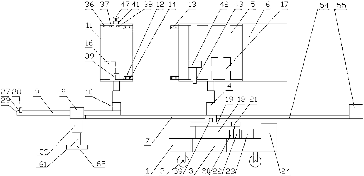
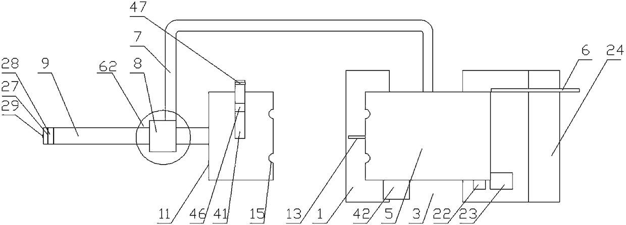
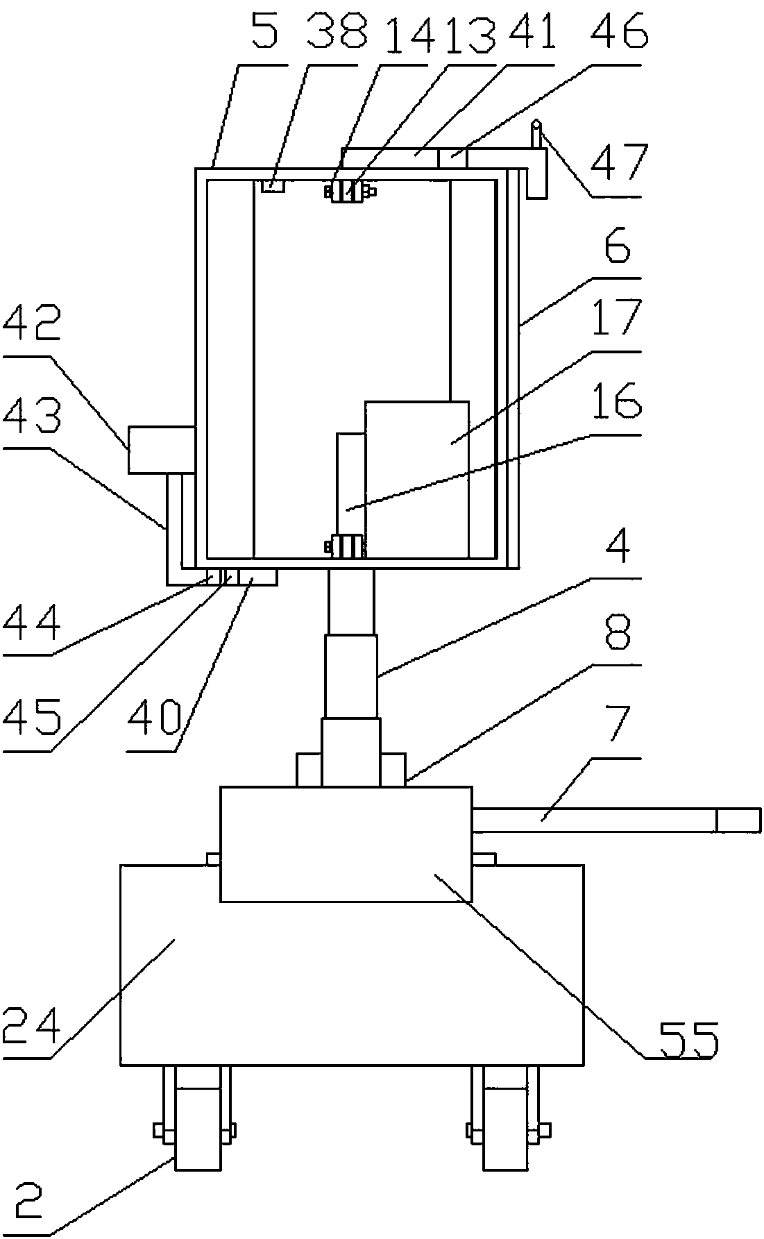
[0047] Embodiment 1: A pole-mounted transformer maintenance system, including a platform 1, a slewing mechanism arranged on the upper part of the platform 1, and a running mechanism 2 arranged at the bottom of the platform 1, and the left and right sides of the platform 1 are provided with recesses Slot 3, the upper part of the slewing mechanism is provided with a right elevating rod 4, the top of the right elevating rod 4 is provided with a right inspection box 5, and the right end of the right inspection box 5 is rotated to install a sealed door 6, and the upper part of the slewing mechanism is close to the edge A half-frame support frame 7 is set, and a fixed sleeve 8 is arranged at the end of the half-frame support frame 7, and a cantilever 9 is slidably arranged in the fixed sleeve 8, and a left elevating rod 10 is fixedly arranged on the upper surface of the right end of the cantilever 9. A left inspection box 11 is arranged on the top of the left elevating rod 10 .
[0...
Embodiment 2
[0062] Embodiment 2: A pole-mounted transformer maintenance system, including a platform 1, a slewing mechanism arranged on the upper part of the platform 1, and a running mechanism 2 arranged at the bottom of the platform 1, and the left and right sides of the platform 1 are provided with recesses Slot 3, the upper part of the slewing mechanism is provided with a right elevating rod 4, the top of the right elevating rod 4 is provided with a right inspection box 5, and the right end of the right inspection box 5 is rotated to install a sealed door 6, and the upper part of the slewing mechanism is close to the edge A half-frame support frame 7 is set, and a fixed sleeve 8 is arranged at the end of the half-frame support frame 7, and a cantilever 9 is slidably arranged in the fixed sleeve 8, and a left elevating rod 10 is fixedly arranged on the upper surface of the right end of the cantilever 9. A left inspection box 11 is arranged on the top of the left elevating rod 10 .
[0...
Embodiment 3
[0070] Embodiment 3: The difference between it and Embodiment 1 and Embodiment 2 is that: both the left elevating rod 10 and the right elevating rod 4 are hydraulic elevating rods.
[0071] The right end of the platform 1 is provided with a draw bar 25 , and a draw hole 26 is provided on the draw bar 25 .
[0072] An elastic layer 48 is provided on the right end surface of the left inspection box 11 and the left end surface of the right inspection box 5 .
[0073] The elastic layer 48 is made of wear-resistant rubber, and the wear-resistant rubber is composed of the following components in parts by weight: 60 parts of polyurethane rubber, 55 parts of acrylic rubber, 26 parts of nitrile rubber, 480 parts of styrene-butadiene rubber, brominated butyl 15 parts of ethylene rubber, 8 parts of polypropylene adiene siloxane, 8 parts of magnesium oxide, 14 parts of carbon black, 6 parts of urethane, 3 parts of polyethylene wax and 2 parts of carbon fiber; due to the use of polyethylen...
PUM
 Abstract
Description
Claims
Application Information
 - R&D
- Intellectual Property
- Life Sciences
- Materials
- Tech Scout
- Unparalleled Data Quality
- Higher Quality Content
- 60% Fewer Hallucinations
Browse by: Latest US Patents, China's latest patents, Technical Efficacy Thesaurus, Application Domain, Technology Topic, Popular Technical Reports.
© 2025 PatSnap. All rights reserved.Legal|Privacy policy|Modern Slavery Act Transparency Statement|Sitemap|About US| Contact US: help@patsnap.com


