Rubber joint for rail vehicle oil pressure damper and rubber formula thereof

A technology of hydraulic shock absorber and rubber joint, which is applied in the direction of shock absorber, spring/shock absorber, shock absorber, etc. It can solve the problems of low adhesion between rubber and metal, short service life, and limited bearing capacity , to achieve the effect of high product performance and long service life

Active Publication Date: 2017-01-18
南通市弘达轨道交通配件有限公司
View PDF10 Cites 5 Cited by
  • Summary
  • Abstract
  • Description
  • Claims
  • Application Information

AI Technical Summary

Problems solved by technology

Due to the high-speed operation of the train, the vibration and noise during operation will continue to increase, which will increase the structural fatigue of the vehicle and reduce the stability and safety reliability of the vehicle.
Rubber joints for oil pressure shock absorbers of locomotives are a product with excellent p

Method used


Image

  • Rubber joint for rail vehicle oil pressure damper and rubber formula thereof

Examples


Embodiment Construction

[0016] In order to deepen the understanding of the present invention, the present invention will be further described below in conjunction with the embodiments and accompanying drawings. The embodiments are only used to explain the present invention and do not constitute a limitation to the protection scope of the present invention.

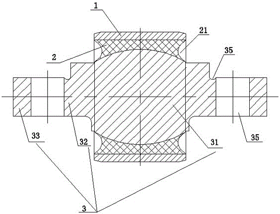
[0017] like figure 1 As shown, the rubber joint for the hydraulic shock absorber of a rolling stock includes an outer jacket layer 1, a rubber layer 2 and a mandrel 3. The mandrel 3 includes a middle part 31, a cylindrical transition part 32 located on both sides of the middle part 31, and a cylindrical transition part 32 located outside the transition part 32. The end portion 33 and the middle portion 31 are partially elliptical, and an arc-shaped groove 34 is provided at the connection between the end portion 33 and the upper side of the transition portion 32, and a through hole is formed on the end portion. Among them, the middle part of the m...


PUM


Abstract

The invention discloses a rubber joint for a rail vehicle oil pressure damper. The rubber joint comprises a coat layer, a rubber layer and a central spindle. The middle portion of the central spindle is sleeved with the rubber layer, the rubber layer is closely bonded with the central spindle, the rubber layer is sleeved with the coat layer, the section of the contact surface of the coat layer and the rubber layer is rectangular, and the side face of the rubber layer is in a concave arc shape. A rubber formula of the rubber layer comprises, by mass, 80-90 parts of natural rubber, 10-20 parts of synthetic rubber, 0.6-1 part of sulfur, 0.8-1.2 parts of benzothiazole-2-thiol, 2.2 parts of 2,2'-dithio-dibenzo thiazole, 0.8-1.2 parts of diphenyl guanidine, 0.4-0.8 part of hexamethylene tetramine, 4-8 parts of hardening resin, 3 parts of zinc oxide, 1 part of stearic acid, 1 part of N-phenyl-N'-cyclohexyl-P-phenylenediamine, 1 part of 2-benzothiazolethiol, 1 part of poly(1,2-dihydro-2,2,4-trimethylquinoline), 1 part of paraffin and 30-50 parts of carbon black. The rubber joint with the rubber layer produced through the formula has strong torsion, radial rigidity, axial rigidity, deflection rigidity and torsion rigidity, and is high in product performance and long in service life.

Description

technical field [0001] The invention relates to the technical field of locomotive accessories, in particular to a rubber joint for an oil pressure shock absorber of a locomotive and a rubber formula thereof. Background technique [0002] With the rapid development of high-speed railways, the speed of trains has increased significantly. Now the speed of high-speed trains has increased from 200km / h to about 350km / h, and will reach more than 400km / h in the near future. Due to the high-speed operation of trains, the vibration and noise during operation are constantly increasing, which increases the structural fatigue of the vehicle and reduces the stability and safety reliability of the vehicle. Rubber joints for oil pressure shock absorbers of locomotives are a product with excellent performance compounded by rubber and metal, which can withstand complex working environments. However, the existing rubber joints have low adhesion between rubber and metal and short service life. ...

Claims


Application Information

Patent Timeline
IPC IPC(8): F16F1/38C08L7/00C08L21/00C08L101/00C08L91/06C08K13/02C08K3/06C08K5/47C08K5/09C08K3/26B29B7/74B29C35/02
CPCB29B7/7461B29C35/02C08K2201/014C08L7/00C08L2205/035F16F1/3605F16F1/38F16F1/3863F16F2224/025F16F2230/14C08L21/00C08L101/00C08L91/06C08K13/02C08K3/06C08K5/47C08K5/09C08K2003/265
Inventor 孙波黄华孙乐
Owner 南通市弘达轨道交通配件有限公司
Why Eureka
Try Eureka