Magnetic-suspending rotary drumfluid damp measuring apparatus

A fluid damping and magnetic levitation technology, which is applied in measuring devices, instruments, flow characteristics, etc., can solve problems such as the reduction of measurement accuracy, and achieve the effect of improving measurement accuracy and precision.

Pending Publication Date: 2017-01-18
SHANGHAI UNIV
View PDF11 Cites 6 Cited by
  • Summary
  • Abstract
  • Description
  • Claims
  • Application Information

AI Technical Summary

Problems solved by technology

[0004] The public number is CN205333469U, a liquid viscosity coefficient measuring instrument. The power motor drives the turntable, and the container containing the measuring liquid is placed on the turntable. The container is passively rotated to make the liquid rotate. There is mechanical damping between the turntable and the container in this structure. friction reduces measurement accuracy

Method used


Image

  • Magnetic-suspending rotary drumfluid damp measuring apparatus
  • Magnetic-suspending rotary drumfluid damp measuring apparatus
  • Magnetic-suspending rotary drumfluid damp measuring apparatus

Examples


Embodiment 1

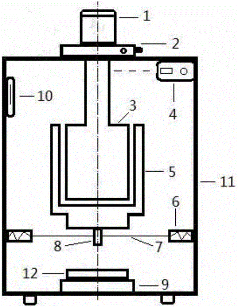
[0034] In this example, see figure 1 and figure 2 , a fluid damping measuring instrument for a magnetic levitation drum, comprising a sealed case 11, a rotating system, a main controller 13, a magnetic levitation actuator and a fluid measuring device, specifically:

[0035]The fluid to be tested is injected into the sealed case 11; the rotation system is composed of a motor 1, a two-dimensional translation support 2 and a cylinder 3, the cylinder 3 has a set diameter, and the motor 1 and the two-dimensional translation support 2 are installed outside the sealed case 11. The drive shaft of the motor 1 is set vertically, the cylinder 3 is set in the sealed case 11 and immersed in the fluid to be tested, the drive shaft of the motor 1 coaxially drives the cylinder 3, so that the motor 1 drives the cylinder 3 to rotate synchronously; the magnetic levitation actuator Including a magnetic levitation drum 5, a magnetic field controller 9 and a tray 12, the magnetic levitation drum ...

Embodiment 2

[0040] This embodiment is basically the same as Embodiment 1, especially in that:

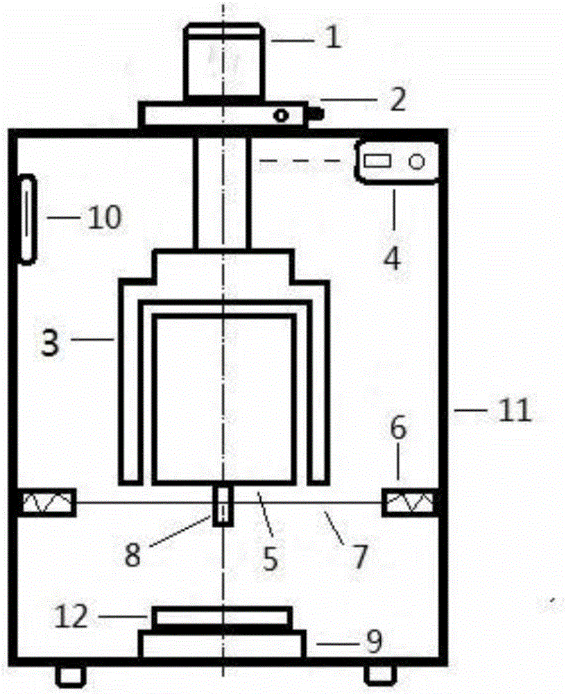
[0041] In this example, see image 3 , the cylinder 3 is a hollow cylindrical device with an open bottom, the magnetic levitation drum 5 is a cylindrical structure, the magnetic levitation drum 5 is inserted into the cylinder 3 from the bottom direction, and is coaxial with the cylinder 3 to form a suit with an intermediate fluid layer In the shaft force transmission device, the inner diameter of the hollow cavity of the cylinder 3 and the outer diameter of the magnetic levitation drum 5 have set dimensions. In this embodiment, the motor 1 drives the magnetic levitation drum 5 to rotate, and the magnetic levitation drum 5 is in the magnetic levitation state. The rotating cylinder 3 drives the fluid to rotate, and the rotating fluid drives the magnetic levitation drum 5 to rotate. Shaft, tension wire 7 measures the torque of magnetic levitation drum 5 or thin rod 8. The motor 1 drives the cyli...

Embodiment 3

[0043] This embodiment is basically the same as the previous embodiment, and the special features are:

[0044] In this example, see Figure 4 , the rotation system adopts the bottom transmission method, the motor 1 and the two-dimensional translation support 2 are installed at the bottom of the sealed cabinet 11, and the cylinder 3 located above is driven from below to rotate; the magnetic levitation actuator adopts the magnetic levitation suction force supply method, and the magnetic field controller 9 is installed On the top of the magnetic levitation drum 5, the magnetic levitation drum 5 is subjected to an upward magnetic levitation suction force from above through the magnetic field controller 9, so that the magnetic levitation drum 5 is suspended in the fluid to be tested.

[0045] In this example, see Figure 4 , the magnetic levitation drum 5 is a hollow cylindrical device with an open bottom, and the cylinder 3 is inserted into the magnetic levitation drum 5 from th...


PUM


Abstract

The invention discloses a magnetic-suspending rotary drumfluid damp measuring apparatus which comprises a motor, a two-dimensional translation support, a cylinder, a rotation speed measuring and controlling instrument, a magnetic-suspending rotary drum, a force moment determinator, a tensile wire, a thin rod, a magnetic field controller, a thermometer, a sealed case and a tray. The motor drives the cylinder to rotate, the rotation speed measuring and controlling instrument controls the rotation speed of the cylinder, the magnetic-suspending rotary drum suspends in a fluid under the effect of a magnetic field produced by the magnetic field controller and is located outside the cylinder, a central shaft is coaxial with the cylinder, the rotating cylinder drives the fluid between the cylinder and the magnetic-suspending rotary drum to rotate, the rotating fluid drives the magnetic-suspending rotary drum to rotate, the thin rod fixed to the magnetic-suspending rotary drum rotates simultaneously, so that the tensile wire wound around the thin rod is slowly wound, finally the force moment of the tensile wire and the force moment of a fluid damp are balanced to make the magnetic-suspending rotary drum stop rotating, and damp coefficients of the fluid are calculated according to the rotation speed, the rotating force moment and other parameters. The magnetic-suspending rotary drumfluid damp measuring apparatus can be used in the field of locomotive manufacturing, aerospace and the like.

Description

technical field [0001] The invention relates to a measuring device for a physical parameter of a fluid, in particular to a measuring device for a fluid damping physical quantity, which is applied in the technical field of fluid mechanics measurement. Background technique [0002] For the damping measurement of fluids such as liquid or air, the commonly used active measurement method is based on motion transmission. The moving body drives the measured fluid to move, and then uses direct or indirect methods to measure the fluid damping force or moment. One of the methods is to convert the motion of the fluid into the motion of other objects, and indirectly measure the damping parameters of the fluid by measuring the motion parameters of the object. During this process, additional motion loss may reduce measurement accuracy and may also increase measurement difficulty. [0003] The public number is CN105185201A, a variable temperature air viscosity coefficient measuring instru...

Claims


Application Information

Patent Timeline
Patent Type & Authority Applications(China)
IPC IPC(8): G01N11/14
CPCG01N11/14
Inventor 李明王叶
Owner SHANGHAI UNIV
Why Eureka
Try Eureka