

A kind of measurement method of antenna amplitude and phase pattern
A technology of directional diagram and antenna, which is applied in the direction of antenna radiation diagram, etc., can solve the problems of difficulty in improving the measurement accuracy of directional diagram and poor measurement accuracy, and achieve the effects of short measurement period, improved measurement efficiency and high measurement efficiency
Inactive Publication Date: 2013-11-20
LEIHUA ELECTRONICS TECH RES INST AVIATION IND OF CHINA
View PDF0 Cites 15 Cited by
- Summary
- Abstract
- Description
- Claims
- Application Information
AI Technical Summary
Problems solved by technology
At the same time, because this method requires a large space, there is generally no shielded dark room in the far-field measurement system. Various interferences and multipath effects of obstacles such as the ground make it difficult to improve the measurement accuracy of the pattern. The measurement accuracy of the far-field pattern usually exceeds 1dB , poor measurement accuracy
For the measurement of the antenna pattern, it is necessary to measure the amplitude and phase characteristics of the antenna efficiently and accurately, and to guide the development and improvement of the antenna in a timely and rapid manner. The above two methods cannot meet these requirements at the same time.
Method used
View moreImage
Smart ImageViewing Examples

Examples
Embodiment
Login to View More PUM
 Abstract
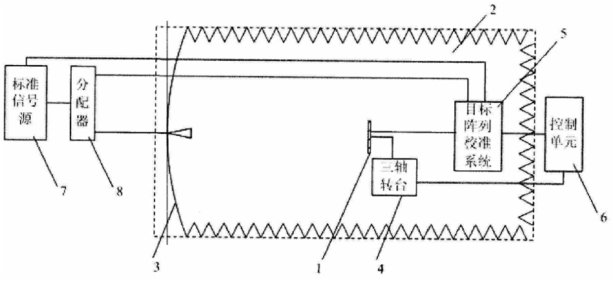
The invention belongs to the antenna pattern measurement technology, and relates to the improvement of the antenna amplitude and phase pattern measurement method. Based on a shielded chamber [2], target array [3], three-axis turntable [4], target array calibration system [5], control unit [6], standard signal source [7] and distributor [8] RF simulation laboratory; the steps of measuring antenna amplitude and phase pattern are as follows; determine the electric axis zero position of the measured antenna [1]; calibrate the polarization plane of the measured antenna [1]; measure the measured antenna [1] in the same Amplitude and phase pattern on the polarization plane corresponding to the azimuth plane and the elevation plane of the three-axis turntable [4]. The invention has short measuring cycle, high measuring efficiency and high measuring precision. It can efficiently and accurately measure the amplitude and phase characteristics of the antenna, and guide the development and improvement of the antenna in a timely and rapid manner.
Description
A Measuring Method of Antenna Amplitude and Phase Pattern technical field The invention belongs to the antenna pattern measurement technology, and relates to the improvement of the antenna amplitude and phase pattern measurement method. Background technique There are two traditional antenna pattern measurement methods: planar near-field measurement method and far-field measurement method. The planar near-field measurement method is to measure the three-dimensional pattern of the antenna in the radiation near-field of the antenna array by using the probe combined with the movement of the precision mobile bracket on a plane parallel to the antenna mouth, and by using computer software to complete a large number of calculations. The conversion relationship between distance and angle, near field and far field is completed, and the direction diagram of the main polarization plane of the antenna is obtained by cutting the three-dimensional pattern on the main polarization plane ...
Claims
Login to View More Application Information
Patent Timeline
 Patent Type & AuthorityPatents(China)
IPC IPC(8): G01R29/10
Inventor邢蕊娜孙国梁张景岩
OwnerLEIHUA ELECTRONICS TECH RES INST AVIATION IND OF CHINA