Minimally-invasive spine surgery robot
A minimally invasive surgery and robot technology, applied in the field of medical machinery, can solve the problem of high control precision and achieve the effects of high precision, strong carrying capacity and large working space
- Summary
- Abstract
- Description
- Claims
- Application Information
AI Technical Summary
Problems solved by technology
Method used
Image

Examples
specific Embodiment approach 1
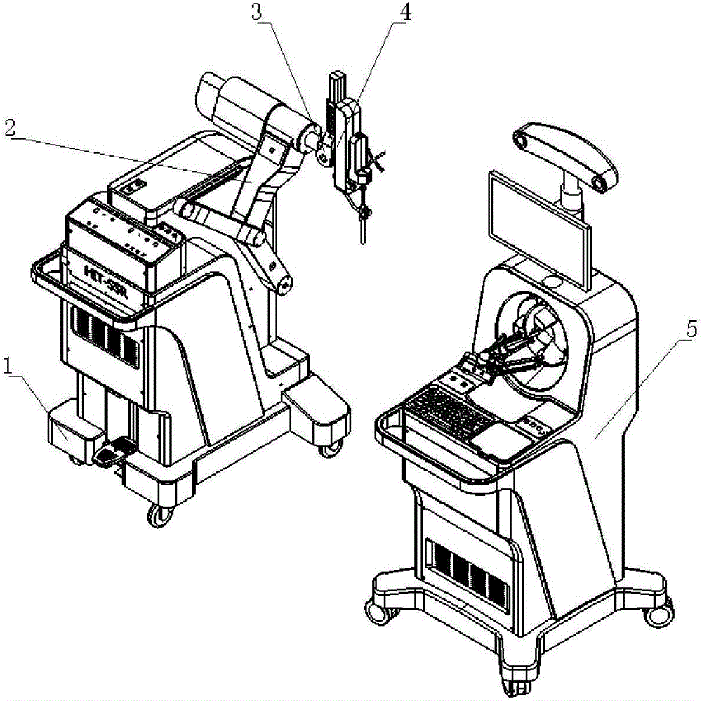
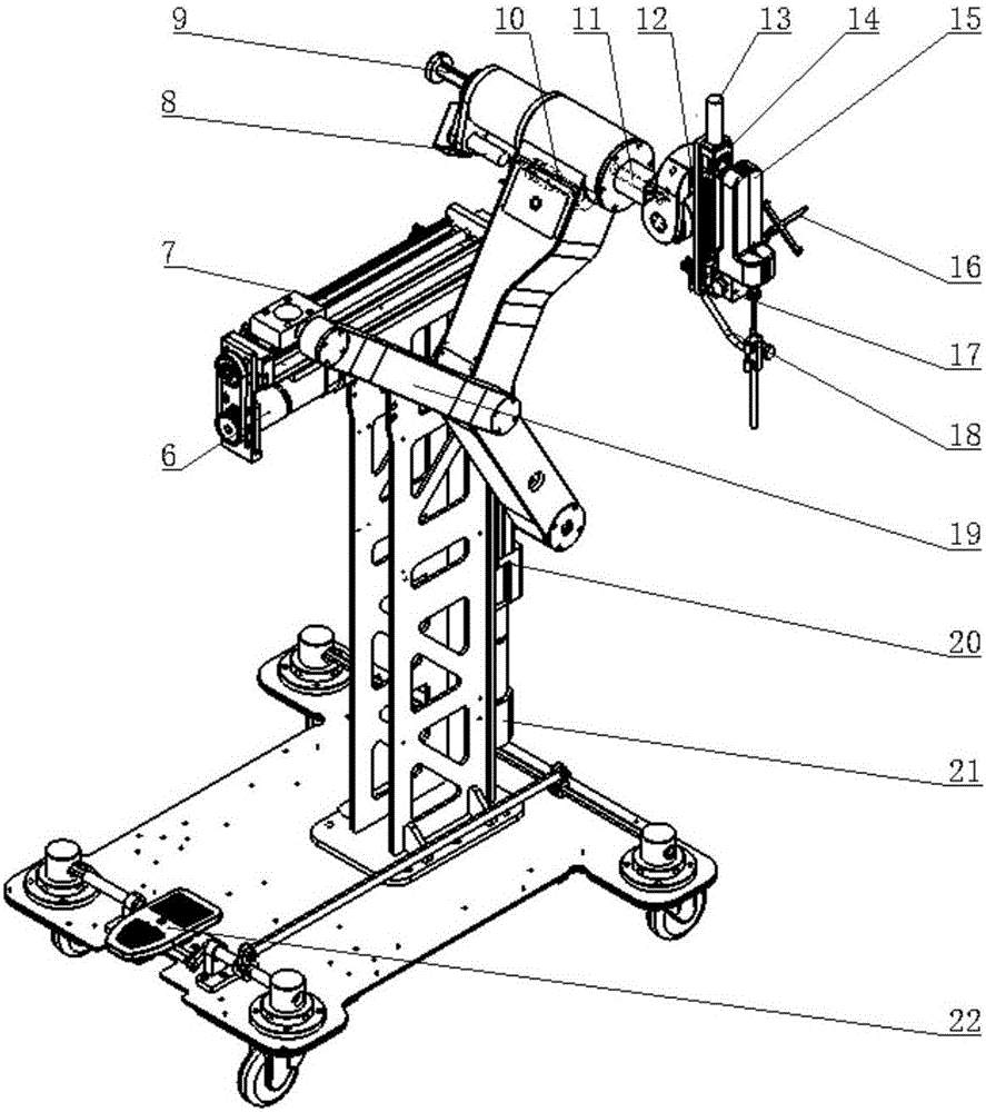
[0009] Specific implementation mode one: combine figure 1 and figure 2 Describe this embodiment. A minimally invasive spinal surgery robot described in this embodiment includes a base 1, a main robot arm 2, a slide table 4, a bracket, a horizontal linear movement mechanism, a vertical linear movement mechanism, a movable joint assembly, and a needle placement mechanism. 15. The middle part of the main mechanical arm 2 is installed on the upper end of the support through the horizontal linear movement mechanism, the support is installed on the base 1, the vertical linear movement mechanism is installed on one side of the support, and the main The lower end of the mechanical arm 2 is connected with the vertical linear movement mechanism, the slide table 4 is installed on the upper end of the main mechanical arm 2 through the movable joint assembly, and the needle setting mechanism 15 is installed on the movable joint assembly. In this embodiment, the horizontal linear movement...
specific Embodiment approach 2
[0010] Specific implementation mode two: combination figure 1 and figure 2 Describe this embodiment. The movable joint assembly of a minimally invasive spinal surgery robot described in this embodiment is composed of a feed screw mechanism, a fifth motor 11 and a rotary joint 3. The feed mechanism includes a third motor 8, a precision ball The screw ball spline assembly 9 and the fourth motor 10, the rotating shaft of the third driving motor 8 is connected with the ball screw part of the precision rice ball screw ball spline assembly 9 through a synchronous pulley, and the precision ball screw ball spline assembly The ball spline part of 9 is connected with the rotating shaft of the fourth motor 10 through the gear set, the precision ball screw ball spline assembly 9 is connected with the slide table 4 through the rotary joint 3, and the rotary joint 3 is connected with the fourth motor 10 through the harmonic reducer and the bevel gear The rotating shaft of the fifth motor ...
specific Embodiment approach 3
[0011] Specific implementation mode three: combination figure 1 and figure 2 This embodiment is described. A six-dimensional sensor 12 is installed on the rotary joint 3 of a robot for minimally invasive spinal surgery described in this embodiment. The six-dimensional sensor 12 can measure the force received when feeding the Kirschner wire and grinding the spine, and has the function of preventing the spine from being drilled. Other components and connections are the same as those in the second embodiment.
PUM
 Abstract
Description
Claims
Application Information
 - R&D
- Intellectual Property
- Life Sciences
- Materials
- Tech Scout
- Unparalleled Data Quality
- Higher Quality Content
- 60% Fewer Hallucinations
Browse by: Latest US Patents, China's latest patents, Technical Efficacy Thesaurus, Application Domain, Technology Topic, Popular Technical Reports.
© 2025 PatSnap. All rights reserved.Legal|Privacy policy|Modern Slavery Act Transparency Statement|Sitemap|About US| Contact US: help@patsnap.com