Constructional engineering concrete mixer

A technology for concrete mixers and construction engineering, which is applied in cement mixing devices, clay preparation devices, and sales of raw material supply devices, etc. It can solve the problems that cleaning water cannot be recycled, cannot meet the use requirements, and products cannot be achieved, and achieves simple structure, Reasonable design, good mixing effect

Inactive Publication Date: 2017-01-25
GUANGXI UNIV
View PDF6 Cites 12 Cited by
  • Summary
  • Abstract
  • Description
  • Claims
  • Application Information

AI Technical Summary

Problems solved by technology

[0002] A concrete mixer is a concrete machine that mixes materials such as sand, gravel, cement and water with a certain ratio into a uniform concrete machine. It usually consists of a motor, a support frame, a mixing drum, and a mixing shaft. Construction machinery greatly improves the construction efficiency, but the mixing tank needs to be cleaned after the concrete mixer is used, and after cleaning most concrete mixers, the cleaning water cannot be recycled, resulting in waste of resources, which cannot meet the needs of use;
[0003] At the same time, the currently used mixer is mainly composed of a mixing shaft and a mixing blade. It is very difficult to improve the efficiency and mixing effect of the mixer only relying on the design of the mixing blade for mixing, so the traditional mixer often has insufficient mixing, stirring Shortcomings such as long time directly lead to the product after stirring cannot achieve the desired result.

Method used


Image

  • Constructional engineering concrete mixer
  • Constructional engineering concrete mixer

Examples


Embodiment Construction

[0015] The following will clearly and completely describe the technical solutions in the embodiments of the present invention with reference to the accompanying drawings in the embodiments of the present invention. Obviously, the described embodiments are only some, not all, embodiments of the present invention. Based on the embodiments of the present invention, all other embodiments obtained by persons of ordinary skill in the art without making creative efforts belong to the protection scope of the present invention.

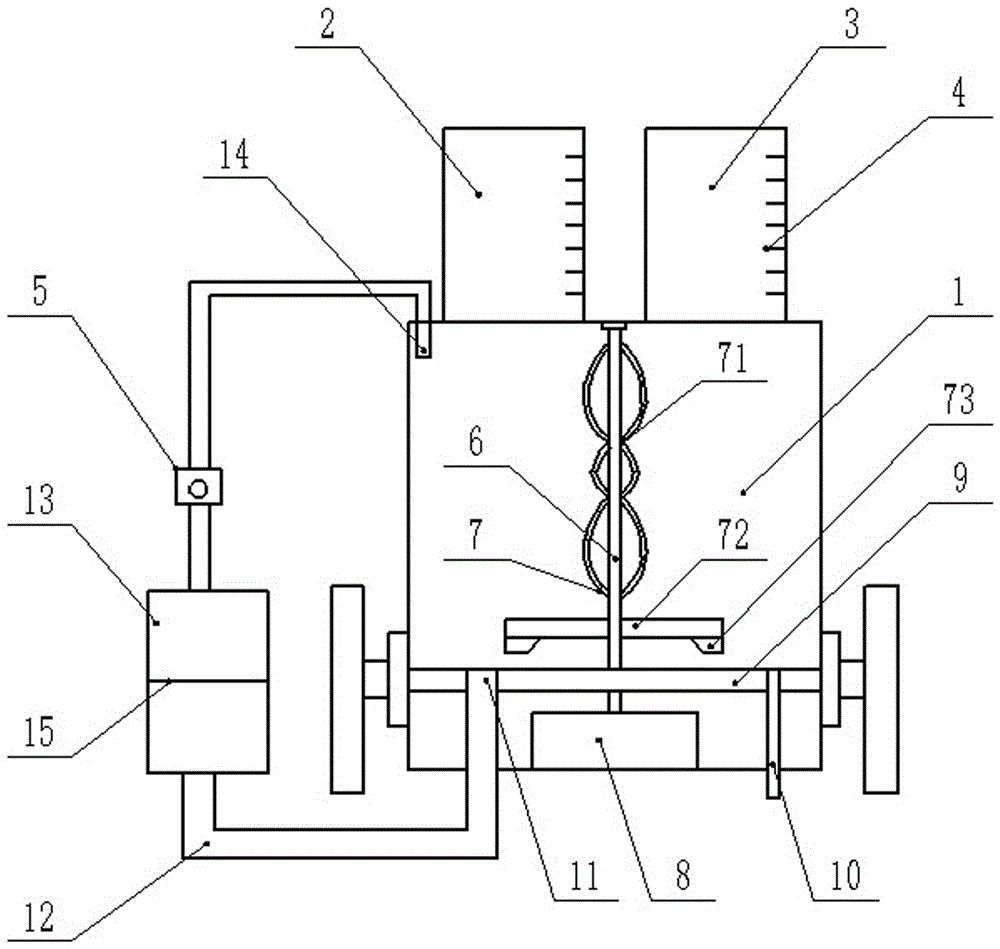
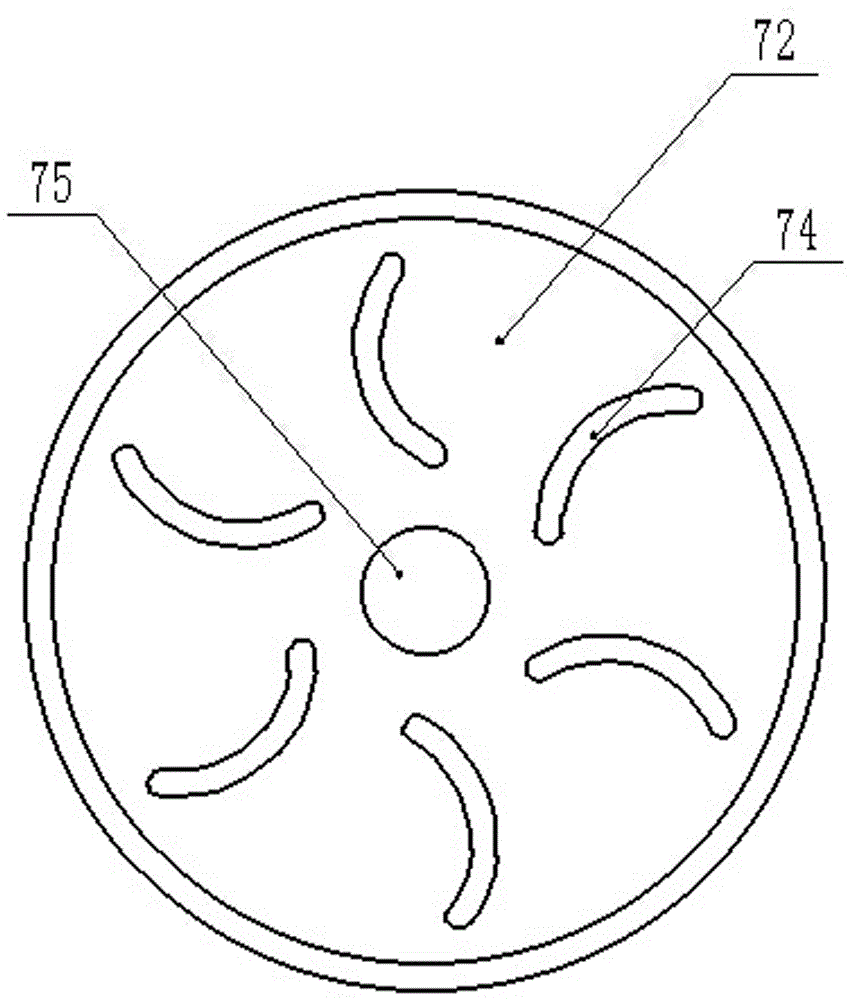
[0016] see Figure 1~2 , in an embodiment of the present invention, a concrete mixer for construction engineering includes a mixing box 1, a stirring shaft 6, a mixing assembly 7, a separation plate 9 and a water outlet pipe 12; Box 2 and water inlet box 3, wherein, feed box 2, water inlet box 3 are all made of transparent material; The surface of described feed box 2, water inlet box 3 is provided with scale line 4; In work, altogether The group personnel ca...


PUM


Abstract

The invention discloses a concrete mixer for construction engineering, which comprises a mixing box, a mixing shaft, a mixing assembly, an isolation plate and a water outlet pipe; a feeding box and a water inlet box are respectively arranged on both sides of the upper part of the mixing box, wherein the feeding Both the feeding box and the water inlet box are made of transparent materials; the surfaces of the feeding box and the water inlet box are all provided with scale lines; inside the mixing box, a stirring shaft and a stirring assembly are arranged, and the stirring shaft is located in the mixing box center, wherein the top of the stirring shaft is provided with a bearing assembly, and the bottom of the stirring shaft is driven and connected to a motor; the stirring assembly includes an annular stirring plate and a stirring paddle; an isolation plate is provided between the agitator and the motor; There is a water outlet, and the right side of the isolation class is provided with a material outlet, wherein the water outlet is connected to the water outlet pipe, and the water outlet pipe is connected to the purified water tank; the water outlet pipe of the purified water tank is provided with a water pump; the invention improves product quality, has high stirring efficiency and Low energy consumption is conducive to saving resources and reducing production costs of enterprises.

Description

technical field [0001] The invention relates to a mixer, in particular to a construction concrete mixer. Background technique [0002] A concrete mixer is a concrete machine that mixes materials such as sand, gravel, cement and water with a certain ratio into a uniform concrete machine. It usually consists of a motor, a support frame, a mixing drum, and a mixing shaft. Construction machinery greatly improves the construction efficiency, but the mixing tank needs to be cleaned after the concrete mixer is used, and after cleaning most concrete mixers, the cleaning water cannot be recycled, resulting in waste of resources, which cannot meet the needs of use; [0003] At the same time, the currently used mixer is mainly composed of a mixing shaft and a mixing blade. It is very difficult to improve the efficiency and mixing effect of the mixer only relying on the design of the mixing blade for mixing, so the traditional mixer often has insufficient mixing, stirring Shortcomings ...

Claims


Application Information

Patent Timeline
Patent Type & Authority Applications(China)
IPC IPC(8): B28C5/16B28C7/06B28C7/12
CPCB28C5/16B28C7/06B28C7/12
Inventor 闫沛浩
Owner GUANGXI UNIV
Why Eureka
Try Eureka