Plate stacking machine

A stacking machine and chuck technology, which is applied in the direction of conveyors, object stacking, transportation and packaging, etc., can solve the problems of high labor costs, uneven stacking of baking trays, and bacterial legacy, so as to improve hygiene and safety, Save labor costs and achieve high degree of automation

Active Publication Date: 2017-01-25
GUANGZHOU LINE AUTOMATION EQUIP
View PDF6 Cites 4 Cited by
  • Summary
  • Abstract
  • Description
  • Claims
  • Application Information

AI Technical Summary

Problems solved by technology

[0003] 1. After the food is removed from the mold, it is necessary to stack the baking trays together for transportation. If the stacking mode of manually grabbing the baking trays is adopted, the human hands will touch the baking trays for a long time, and it is easy to produce bacteria left on the baking trays, which greatly reduces the food quality. health and safety;
[0004] 2. Under the plan of higher production capacity, the working frequency of each process is also accelerated accordingly. If the stacking mode of manually grabbing the baking tray is adopted, the stacking speed will be slower, and the tray supply speed of subsequent posts will be correspondingly slower, thus greatly reducing Improved food processing efficiency;
[0005] 3. Due to the large number of stacked baking trays, if the stacking mode of manually snatching the baking trays is adopted, it is difficult to avoid manual stacking mistakes, resulting in uneven stacking of the baking trays, which affects the transportation and use of subsequent stations;
[0006] 4. If the stacking mode of manually snatching the baking pan is adopted, a large amount of manual work is required for the stacking operation, and the labor cost is high

Method used


Image

  • Plate stacking machine
  • Plate stacking machine
  • Plate stacking machine

Examples


Embodiment Construction

[0044] For the convenience of those skilled in the art to understand, the present invention will be further described in detail below in conjunction with the accompanying drawings and embodiments.

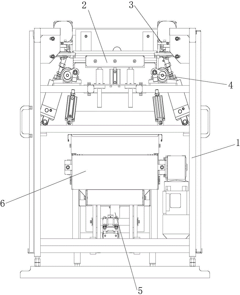
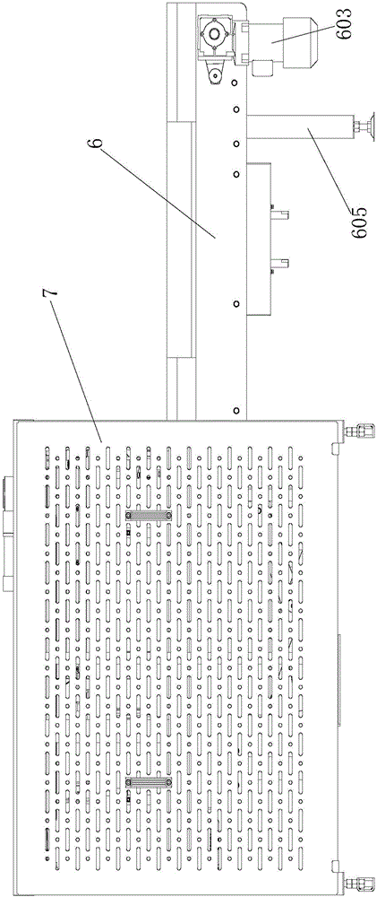
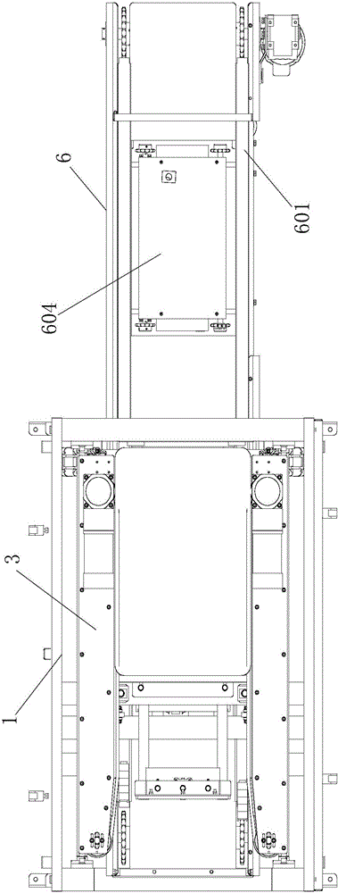
[0045] Such as Figure 1 to Figure 3 As shown, the disc stacking machine includes a frame 1, a positioning mechanism 2, a chuck mechanism 3, a disc receiving mechanism 4, a lifting mechanism 5 and an output mechanism 6, and the positioning mechanism 2, the chucking mechanism 3 and the disc receiving mechanism 4 are all installed On the upper end of the frame 1, one end of the chuck mechanism 3 is connected with the positioning mechanism 2, and the other end of the chuck mechanism 3 is connected with the tray mechanism 4; the lifting mechanism 5 is installed at the lower end of the frame 1, and the The lifting mechanism 5 is installed below the receiving mechanism 4 , and the lifting mechanism 5 is connected with the output mechanism 6 . Specifically, when the empty baking tray is ...


PUM


Abstract

The invention discloses a plate stacking machine which comprises a rack, a locating mechanism, a plate clamping mechanism, a plate catching mechanism, a lifting mechanism and an output mechanism, wherein the locating mechanism, the plate clamping mechanism and the plate catching mechanism are all mounted at the upper end of the rack; one end of the plate clamping mechanism is connected with the locating mechanism; the other end of the plate clamping mechanism is connected with the plate catching mechanism; the lifting mechanism is mounted at the lower end of the rack; the lifting mechanism is mounted below the plate catching mechanism; the lifting mechanism is connected with the output mechanism. By the adoption of mechanical equipment, the plate stacking machine automatically stacks plates, replaces a conventional plate stacking mode that the plates are grabbed artificially, is high in automation degree and high in plate stacking speed, and greatly increases the speed of stacking of food baking plates.

Description

technical field [0001] The invention relates to food processing equipment, in particular to a stacking machine. Background technique [0002] During the various processing procedures of moon cakes, flower cakes and other foods, when the products are demolded, the empty baking trays usually need to be stacked together and transported to the designated position by the conveyor line, so as to facilitate the circulation of subsequent stations. use. In the traditional stacking operation of flat-bottomed baking trays, after the product is demolded, the empty baking trays are usually stacked one by one manually, and manually transported to the designated location for use; however, these operating modes have the following defects: [0003] 1. After the food is removed from the mold, it is necessary to stack the baking trays together for transportation. If the stacking mode of manually grabbing the baking trays is adopted, the human hands will touch the baking trays for a long time,...

Claims


Application Information

Patent Timeline
Patent Type & Authority Applications(China)
IPC IPC(8): B65G57/03
CPCB65G57/035B65G2201/0258
Inventor 唐德权
Owner GUANGZHOU LINE AUTOMATION EQUIP
Why Eureka
Try Eureka