Electroplating device

A technology of electroplating device and electroplating tank, which is applied in the direction of plating tank, electrolysis process, electrolysis components, etc., can solve the problems of front and back shaking of the circuit board.

Active Publication Date: 2017-01-25
UNIVERSAL CIRCUIT BOARD EQUIP CO LTD
View PDF12 Cites 4 Cited by
  • Summary
  • Abstract
  • Description
  • Claims
  • Application Information

AI Technical Summary

Problems solved by technology

[0004] The purpose of the present invention is to provide a stable electroplating device for transferring circuit boards, which aims to solve the problem of shaking back and forth when transferring circuit boards in the prior art

Method used


Image

  • Electroplating device
  • Electroplating device
  • Electroplating device

Examples


Embodiment Construction

[0026] In order to make the object, technical solution and advantages of the present invention clearer, the present invention will be further described in detail below in conjunction with the accompanying drawings and embodiments. It should be understood that the specific embodiments described here are only used to explain the present invention, not to limit the present invention.

[0027] It should be noted that when an element is referred to as being “fixed” or “disposed on” another element, it may be directly on the other element or be indirectly on the other element. When an element is referred to as being "connected to" another element, it can be directly connected to the other element or indirectly connected to the other element.

[0028] It should also be noted that the orientation terms such as left, right, up, and down in this embodiment are only relative concepts or refer to the normal use state of the product, and should not be regarded as limiting.

[0029] The el...


PUM


Abstract

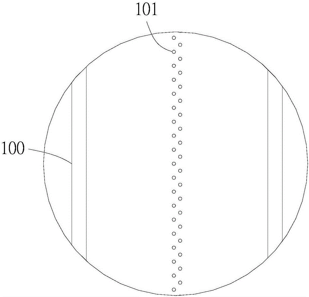
The invention relates to an electroplating device. The electroplating device comprises an electroplating bath, a delivery mechanism and multiple groups of jet flow components arranged in the electroplating bath, wherein each jet flow component comprises two jet flow pipes vertically arranged side by side; a gap for passing of a circuit board is left between the two jet flow pipes; at least one row of injection hole sets distributed in the axial direction of each jet flow pipe is arranged at the inner side of the jet flow pipe; the rows of injection hole sets of the two jet flow pipes are arranged opposite to each other; each injection hole set comprises a plurality of injection holes; and the injection holes of the injection hole sets positioned in the opposite rows are arranged in the axial direction of the jet flow pipe in a staggered manner. The injection hole is of a hole-like structure, so that the circuit board can not be scratched; when the injection holes of the opposite rows are staggered, opposite injection of the injection holes of the two rows can be avoided, thus improving the hole debubbling effect; and impact forces of electroplating solutions injected by the injection holes of the two opposite rows on the circuit board are the same, so that circuit board swing and jet flow pipe collision can be effectively avoided, and the jet flow pipe can be prevented from scratching the circuit board.

Description

technical field [0001] The invention relates to the field of circuit board electroplating, and more specifically relates to an electroplating device. Background technique [0002] The electroplating process of circuit boards involves multiple processes for surface treatment of circuit boards, such as spray cleaning, water drying, and electroplating. In the electroplating process, the circuit board is soaked in the electroplating tank, and the surface of the circuit board is electroplated by the electroplating device. When the dry circuit board is immersed in the electroplating tank, bubbles are easy to form on the surface and holes of the circuit board. These bubbles affect the electroplating quality of the circuit board. . In the prior art, a spray assembly for spraying electroplating solution is usually installed in the electroplating pool, and the injection pressure of the electroplating solution is provided by a pump, and the electroplating solution is sprayed through t...

Claims


Application Information

Patent Timeline
Patent Type & Authority Applications(China)
IPC IPC(8): C25D5/08C25D7/00C25D17/02C25D21/10
CPCC25D5/08C25D7/00C25D17/02C25D21/10
Inventor 陈德和
Owner UNIVERSAL CIRCUIT BOARD EQUIP CO LTD
Why Eureka
Try Eureka