
Air purification equipment and air purification method

A kind of air purification equipment and air purification technology, applied in the direction of mechanical equipment, air humidification system, lighting and heating equipment, etc., can solve the problems that the air purification effect cannot be achieved, the concentration distribution of air quality pollutants cannot be fully presented, and the main pollution source can be found.

Inactive Publication Date: 2017-01-25
LG ELECTRONICS CHINA RANDD CENT SHANGHAI CO LTD
View PDF7 Cites 26 Cited by
  • Summary
  • Abstract
  • Description
  • Claims
  • Application Information

AI Technical Summary

Problems solved by technology

[0003] Since the current air purifier does not have the function of monitoring air quality and removal effect, if the user does not install a gas analyzer, it is impossible to consider the effect of the air purifier, and it is impossible to clearly know the environmental quality in the room
Therefore, turning on the air purifier for a long time not only causes waste of resources, but also fails to achieve the desired air purification effect.
[0004] Although air quality sensors are installed in some air purifiers, mainly including particle sensors and gas sensors, which can identify the concentration of dust particles and PM2. Display of the air quality level in the form of
This kind of air purifier not only tests the types of gases and has limited accuracy, but also tests the air quality at a certain point in the room or in a small area, but cannot fully present the air quality of the entire room and the concentration distribution of pollutant gases, let alone help users Locate the main source of pollution

Method used


Image

  • Air purification equipment and air purification method
  • Air purification equipment and air purification method
  • Air purification equipment and air purification method

Examples


Embodiment Construction

[0049] The following will clearly and completely describe the technical solutions in the embodiments of the present invention with reference to the accompanying drawings in the embodiments of the present invention. Obviously, the described embodiments are only some, not all, embodiments of the present invention. Based on the embodiments of the present invention, all other embodiments obtained by persons of ordinary skill in the art without making creative efforts belong to the protection scope of the present invention.

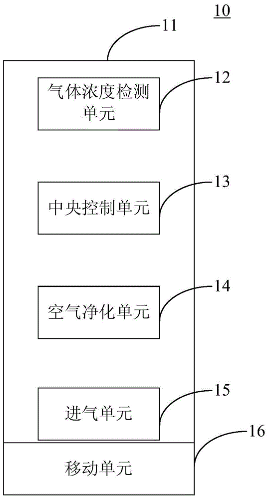
[0050] figure 1 Shown is a schematic structural view of an air purification device 10 according to an embodiment of the present invention. Such as figure 1 As shown, the air purification device 10 includes a housing 11 , a mobile unit 16 , a gas concentration detection unit 12 , a central control unit 13 , an air purification unit 14 and an air intake unit 15 disposed in the housing 11 .

[0051] The gas concentration detection unit 12 is used to detect the ...


PUM


Abstract

The invention provides air purification equipment and an air purification method. The air purification equipment comprises a shell, a mobile unit and a gas concentration detection unit, a central control unit, a gas inlet unit and an air purification unit which are arranged in the shell; the gas concentration detection unit is used for detecting the gas integral concentration of an optical path in a monitored area; the central control unit is used for determining the varieties of air pollutants and concentration reconstruction graphs of different varieties of air pollutants and acquiring geographic position information of the area where the concentration of the air pollutants exceeds the standard most seriously in the monitored area and generating a driving signal when the concentration of the air pollutants exceeds the standard; the mobile unit is used for moving to the area where the concentration of the air pollutants exceeds the standard most seriously in the monitored area under control of the driving signal; the gas inlet unit controls the gas inlet volume under control of the driving signal; the air purification unit comprises multiple layers of filter screens used for purifying air entering the air purification equipment. Accordingly, fixed-point air purification can be achieved.

Description

technical field [0001] The invention relates to the fields of air quality detection and air purification, in particular to an air purification device and an air purification method based on the concentration distribution of air pollutants. Background technique [0002] At present, the air purifiers on the market are mainly based on one or several technologies such as adsorption technology, negative (positive) ion technology, catalytic technology, photocatalyst technology, superstructure photomineralization technology, HEPA high-efficiency filtration technology, electrostatic dust collection technology, etc. To achieve the effect of air purification, in addition, it does not have the function of monitoring ambient air quality and removal effect. [0003] Since the current air purifier does not have the function of monitoring air quality and removal effect, if the user does not install a gas analyzer, it is impossible to consider the effect of the air purifier, and it is impos...

Claims


Application Information

Patent Timeline
Patent Type & Authority Applications(China)
IPC IPC(8): F24F6/00F24F11/02F24F13/28
CPCF24F8/10
Inventor 张佩佩彭培源
Owner LG ELECTRONICS CHINA RANDD CENT SHANGHAI CO LTD
Learn More