Non-contact throttle position sensor

A throttle position, non-contact technology, applied in the direction of converting sensor output, using electric/magnetic devices to transmit sensing components, instruments, etc., can solve the problem of not meeting the output accuracy requirements of the throttle position sensor, fast wear of the sealing ring, Insufficient output accuracy and other problems, to achieve the effect of novel structure, improved accuracy, and good working stability

Inactive Publication Date: 2017-01-25
CHONGQING BEST ELECTRONICS TECH
View PDF11 Cites 0 Cited by
  • Summary
  • Abstract
  • Description
  • Claims
  • Application Information

AI Technical Summary

Problems solved by technology

[0004] However, because the Hall chip itself is very susceptible to the interference of the external magnetic field, the output accuracy of this type of non-contact throttle position sensor is insufficient, which cannot meet the output accuracy requirements of the throttle position sensor; The non-contact throttle position sensor of the chip has a gap between the rotor and the sensor housing. In order to seal the two, a sealing ring is required between the rotor and the sensor housing. The traditional sealing ring is an annular gasket The contact surface of the rotor and the sensor housing is a flat structure, which only has a sealing effect in the axial direction, and the friction is large, so the wear speed of the sealing ring is fast and the service life is short. Once damaged, it will cause water or The pouring of impurities such as mud will cause irreversible damage to the sensor

Method used


Image

  • Non-contact throttle position sensor
  • Non-contact throttle position sensor
  • Non-contact throttle position sensor

Examples


Embodiment Construction

[0029] The present invention will be further described below in conjunction with embodiment and accompanying drawing.

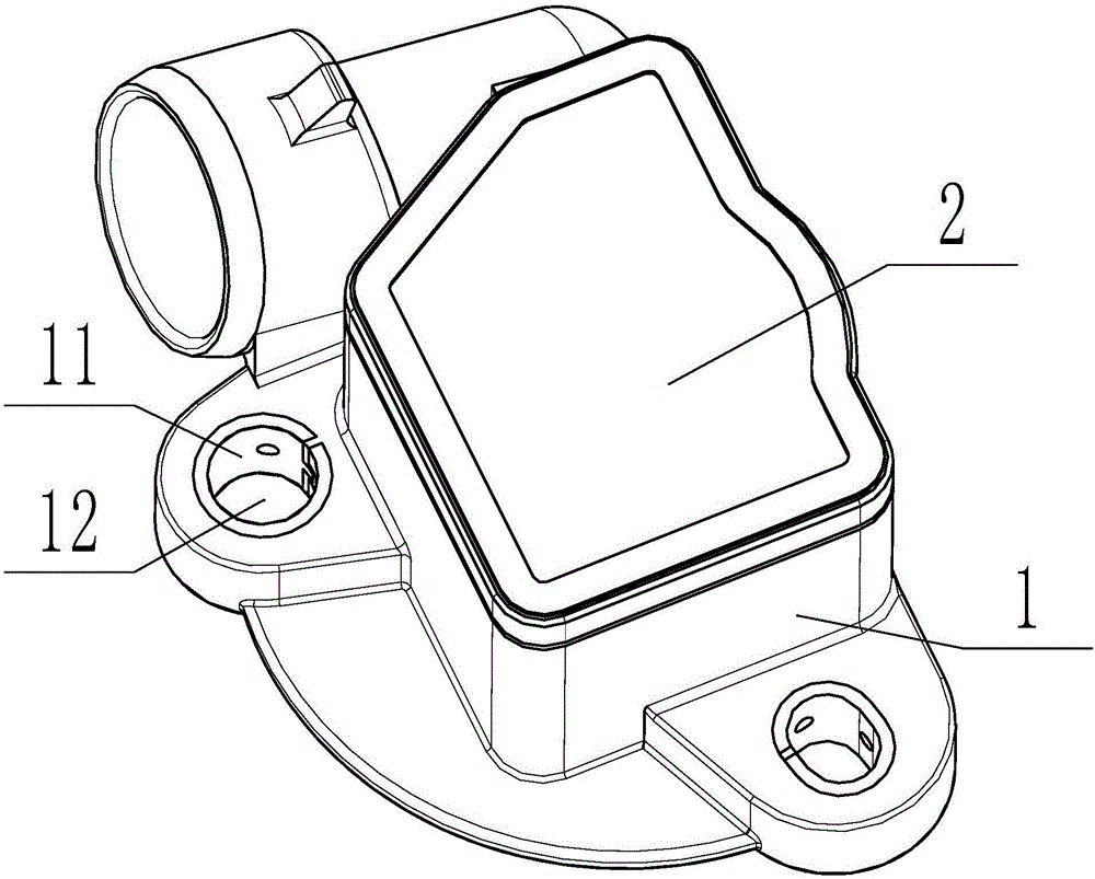
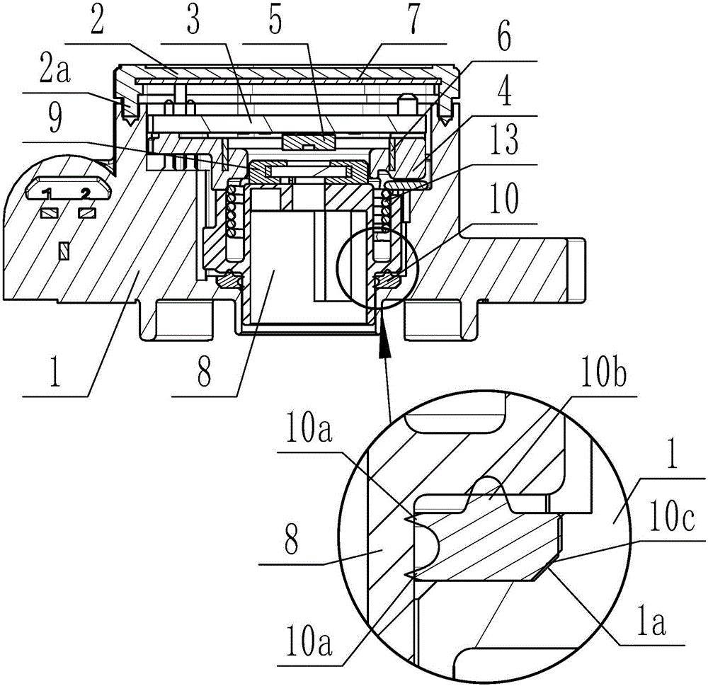
[0030] Such as figure 1 and figure 2 As shown, a non-contact throttle position sensor includes a housing 1 and a cover plate 2 fastened on the housing 1. A rotor 8, a limiter, and a rotor 8 are sequentially arranged inside the housing 1 from bottom to top. The bit board 4 and the circuit board 3 are provided with a reset twist yellow 13 for resetting the rotor 8. One end of the reset twist yellow 13 is overlapped with the rotor 8, and the other end is connected with the housing 1 lap.

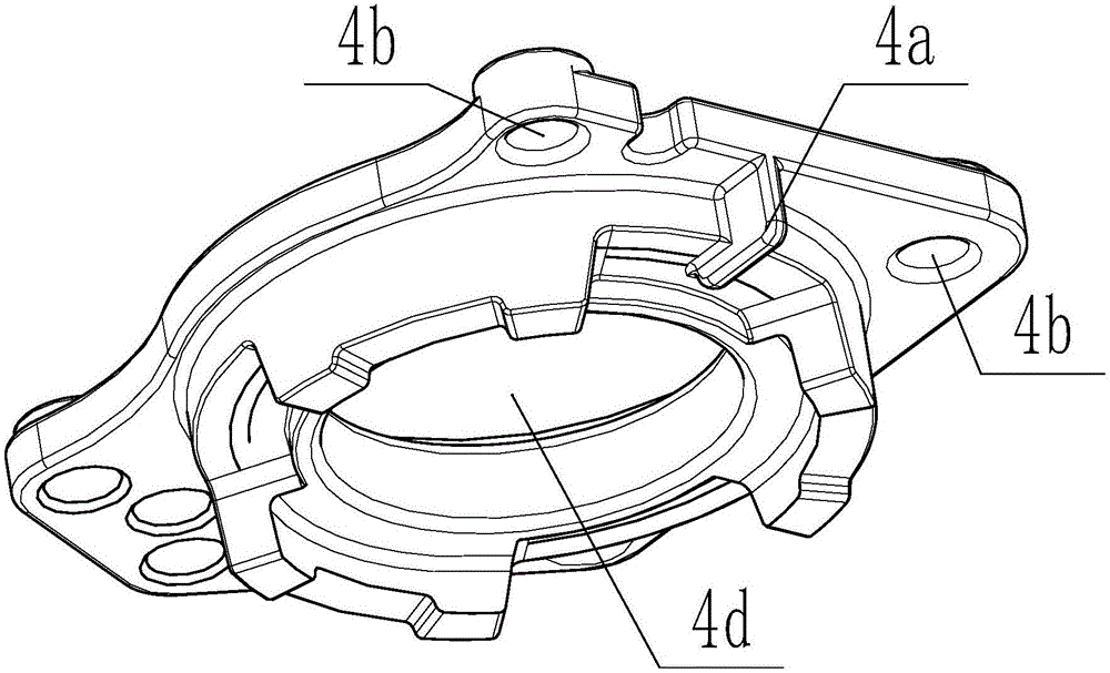
[0031] See figure 2 , Figure 4 and Figure 5 , the rotor 8 is provided with a magnetic element 9, and the lower surface of the circuit board 3 is provided with a Hall chip 5 adapted to the magnetic element 9, and a gap is left between the Hall chip 5 and the magnetic element 9. gap, the limiting plate 4 has a hollow portion 4d, and the Hall chip 5 and the magnetic ele...


PUM


Abstract

The invention discloses a non-contact throttle position sensor. The non-contact throttle position sensor comprises a casing and a cover plate, wherein a rotor, a limiting plate and a circuit board are sequentially arranged in the casing from bottom to top, and a reset torsion spring used for enabling the rotor to be reset is arranged outside the rotor; a magnetic element is arranged on the rotor, a Hall chip is arranged on the circuit board, a gap is reserved between the Hall chip and the magnetic element, and a shielding plate is arranged on the cover plate; a sealing ring is arranged between the rotor and the casing, two lips are arranged on the inner side surface of the sealing ring, and a circle of annular bulges are arranged on the upper surface of the sealing ring. With the adoption of the structure, the non-contact throttle position sensor has excellent sealing performance, impurities are prevented from entering the non-contact throttle position sensor and damaging internal elements, meanwhile, the influence of outside disturbing magnetic fields on the Hall chip is effectively shielded, signal drift is avoided, the precision of output signals of the Hall chip is greatly improved, and accordingly, the non-contact throttle position sensor is applicable to a harsh working environment, has good working stability, avoids mechanical wear and has longer service life.

Description

technical field [0001] The invention belongs to the technical field of engine control, and in particular relates to a non-contact throttle position sensor. Background technique [0002] The throttle valve is a controllable valve that controls the air to enter the engine. After the gas enters the intake pipe, it will mix with gasoline to form a combustible mixture, which will be burned to do work. The air filter is connected to the throttle, the intake pipe is connected to the bottom, and the engine block is usually called the throat of the car engine. The throttle valve works mainly through the communication between the throttle valve position sensor and the ETC, and feeds back the working state of the throttle valve to the ETC, which is the intention of the driver. Emission requirements, vehicle performance. The throttle position sensor is a component in the engine management system. It is installed on the throttle body to detect the throttle opening information and feed ...

Claims


Application Information

Patent Timeline
Patent Type & Authority Applications(China)
IPC IPC(8): G01D5/14
CPCG01D5/145
Inventor 杨大明汤伟张建
Owner CHONGQING BEST ELECTRONICS TECH
Why Eureka
Try Eureka