
Method for determining structure tolerance of sparsely-configured antenna array based on radiation field and scattering field

A technology for array antennas and determination methods, applied in special data processing applications, instruments, electrical digital data processing, etc., can solve problems such as antenna structure tolerance, antenna structure error, difficulty in quickly determining and distributing, etc., to improve accuracy and speed, Good applicability, avoiding the effect of limitations

Active Publication Date: 2017-01-25
XIDIAN UNIV
View PDF7 Cites 7 Cited by
  • Summary
  • Abstract
  • Description
  • Claims
  • Application Information

AI Technical Summary

Problems solved by technology

[0005] The purpose of the present invention is to provide a radiation and scattering-oriented method for determining the structure error of sparsely arranged array antennas, so as to effectively solve the problem that it is difficult to quickly determine and allocate antenna structure tolerances in the design of sparsely arranged array antenna structures, and can guide sparse Arranging array antenna element position installation accuracy and formulation and allocation of array flatness, and evaluation of antenna structure scheme

Method used


Image

  • Method for determining structure tolerance of sparsely-configured antenna array based on radiation field and scattering field
  • Method for determining structure tolerance of sparsely-configured antenna array based on radiation field and scattering field
  • Method for determining structure tolerance of sparsely-configured antenna array based on radiation field and scattering field

Examples


Embodiment Construction

[0059] Below in conjunction with accompanying drawing and embodiment the present invention will be further described

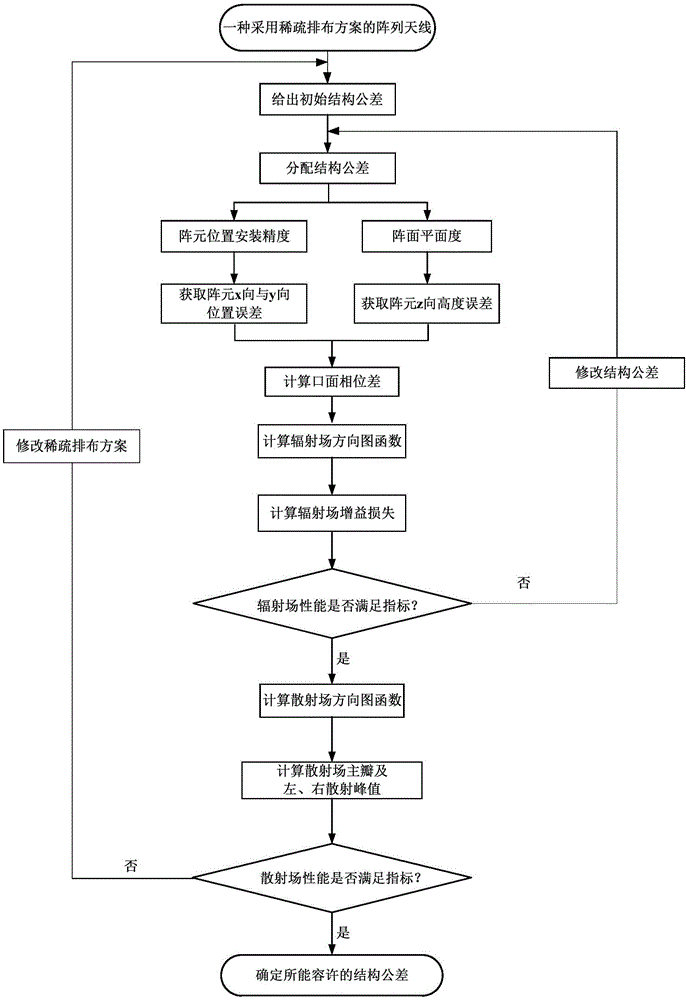
[0060] refer to figure 1 , the present invention is a method for determining the structural tolerance of sparsely arranged array antennas oriented to radiation and scattering, and the specific steps are as follows:

[0061] Step 1, determine the structural parameters, electromagnetic parameters and sparse arrangement matrix of the sparsely arranged array antenna.

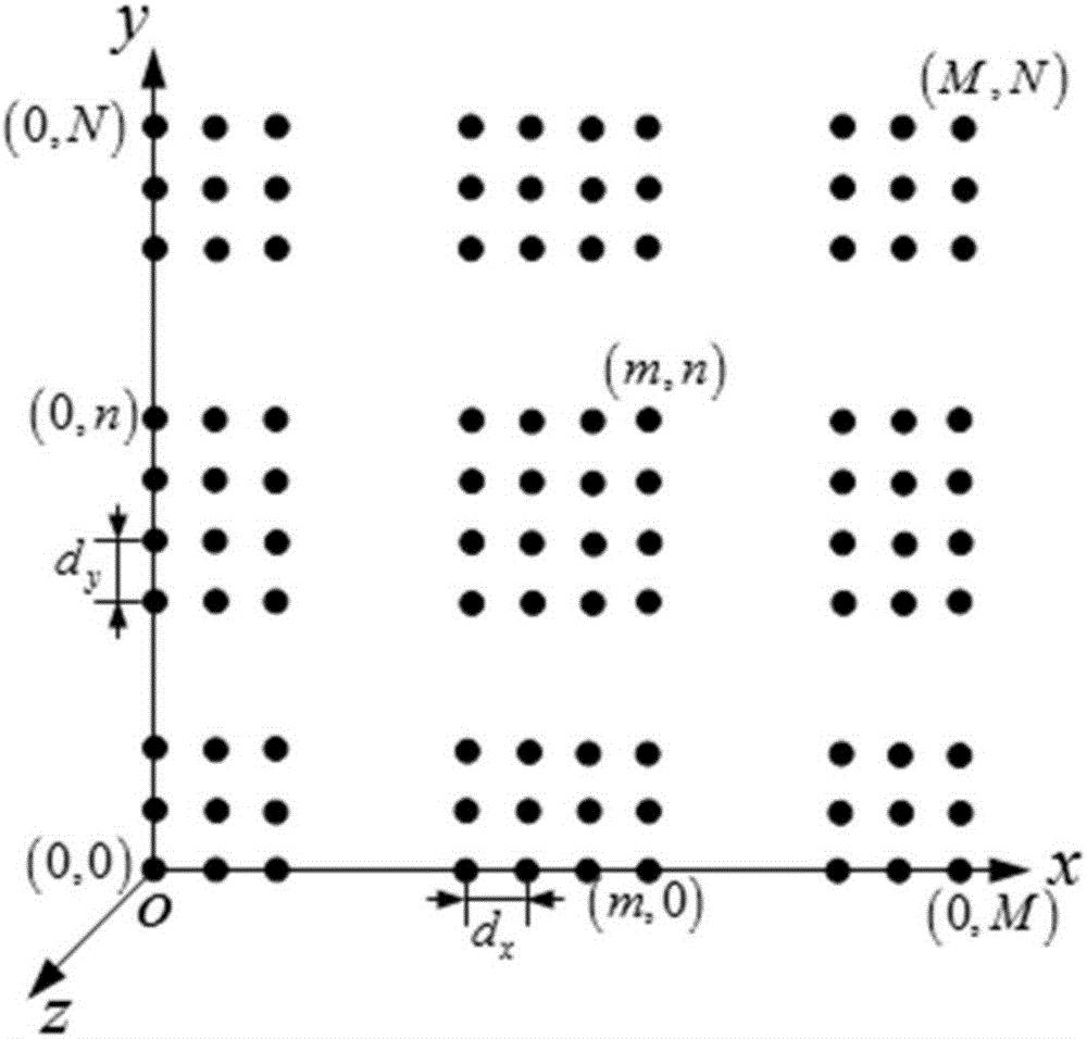
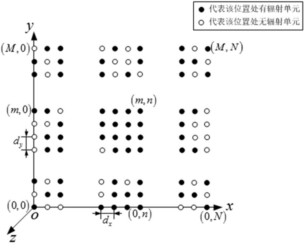
[0062] 1.1. Determine the structural parameters of the sparsely arranged array antenna, that is, to obtain the number of rows M, the number of columns, and the distance between array elements in the x direction d x and y-element spacing d y , the number of the radiation unit in the array is (m,n), where m and n are the numbers of the radiation unit in the x and y directions respectively, and the lower left corner of the array is the starting number, that is, the radiation at the lower left corner ...


PUM


Abstract

The invention discloses a method for determining a structure tolerance of a sparsely-configured antenna array based on a radiation field and a scattering field. The method comprises the steps that a structure, electromagnetic working parameters and a sparsely-configured matrix of the sparsely-configured antenna array are determined, and an initial structure tolerance is provided; the structure tolerance is allocated as the position installation precision of array elements in the plane where a sparse array surface is located and the planeness of a normal array surface of the sparse array surface where the array elements are located; a random number of array element position installation errors and a random number of array surface planeness errors are acquired; a radiation field space phase difference of every two adjacent radiation units in the sparse array at a target is calculated to obtain an antenna radiation field oral surface phase difference; an antenna radiation field direction diagram is calculated; the deterioration degree of a phase antenna gain relative to design indexes is calculated; whether the design requirements are met or not is judged; an antenna scattering field oral surface phase difference and a scattering field direction diagram are calculated, and electrical property parameters of the scattering field are calculated; whether the design requirements are met or not is judged. According to the method, the processing and mounting difficulty can be reduced, the development cost can be reduced, and the development cycle can be shortened.

Description

technical field [0001] The invention belongs to the field of radar antennas, and in particular relates to the determination and distribution of sparsely arranged array antenna structure design and manufacturing tolerances, which can be used to guide the rapid determination of sparsely arranged array antenna structure tolerances. Background technique [0002] Antennas are widely used in radio systems such as communications, broadcasting, television, radar, and navigation. They play the role of spreading radio waves and are an indispensable device for effectively radiating and receiving radio waves. With the development of science and technology, ordinary antennas are no longer enough to meet the needs, especially for guided weapons and electronic countermeasures in the military field, which put forward strict requirements for radar antennas. Array antenna has been widely used in various radar systems and has become the mainstream of radar development due to its advantages of ...

Claims


Application Information

Patent Timeline
IPC IPC(8): G06F17/50
CPCG06F30/20
Inventor 王从思颜语喆胡核算许谦周金柱朱诚王伟宋立伟段宝岩平丽浩袁帅
Owner XIDIAN UNIV
Learn More