Composite diaphragm for lithium ion battery for lithium-sulfur battery and preparation method and application of composite diaphragm for lithium ion battery

A lithium-ion battery and composite diaphragm technology, applied in the field of electrochemical energy storage, can solve the problems of limited infiltration and adsorption capacity, large internal polarization of battery devices, and reduced safety performance, so as to improve electrochemical performance and safety performance, and improve thermal performance. Effects of stability and safety performance, excellent cycle performance

Inactive Publication Date: 2017-01-25
INST OF METAL RESEARCH - CHINESE ACAD OF SCI
View PDF3 Cites 33 Cited by
  • Summary
  • Abstract
  • Description
  • Claims
  • Application Information

AI Technical Summary

Problems solved by technology

However, the current commercialized separator has limited electrolyte infiltration and adsorption capacity due to its polymer material characteristics, and is an electronic insulator, so its contact resistance with the electrolyte and electrode interface is relatively large, resulting in the internal polarization of the entire battery device. Larger, thus affecting the service life and power performance of the battery; in addition, the commercialized separator is a polymer material, and its high-temperature stability is generally poor, which is difficult to meet the safe use of the battery under high-temperature abuse, and the porous structure is easily damaged by lithium. The dendrites are punctured, causing a short circuit between the positive and negative electrodes of the battery, causing the battery to burn or even explode
[0004] For the improvement of the electrochemical performance and high-temperature safety performance of the separator, the current research solutions are usually divided into

Method used


Image

  • Composite diaphragm for lithium ion battery for lithium-sulfur battery and preparation method and application of composite diaphragm for lithium ion battery
  • Composite diaphragm for lithium ion battery for lithium-sulfur battery and preparation method and application of composite diaphragm for lithium ion battery
  • Composite diaphragm for lithium ion battery for lithium-sulfur battery and preparation method and application of composite diaphragm for lithium ion battery

Examples


Embodiment 1

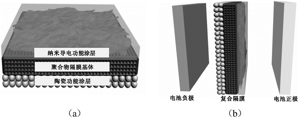
[0032] In this embodiment, the graphene nano-conductive functional coating and the alumina ceramic functional coating are respectively coated on both sides of the polypropylene diaphragm substrate to form a battery composite diaphragm, and it is assembled in a lithium-sulfur battery. The process is as follows:

[0033] 1. Preparation of single-functional graphene nano-conductive functional coating: first dissolve 1.016g of polyvinylidene fluoride (PVDF) in 253g of N-methylpyrrolidone (NMP) solvent, and stir with a mechanical stirrer at a rate of 700 rpm 1h to uniform, and configure a PVDF solution with a concentration of 0.4wt.%; add 4g of graphene powder obtained by the intercalation exfoliation method into the PVDF solution (the number of graphene layers is 3 to 7 layers, and the typical size of graphene is 5 to 7 layers). 10 μm), continue to use a mechanical stirrer to stir at a rate of 1000 rpm for 1 h to uniformly disperse the graphene in the PVDF solution, and prepare a g...

Embodiment 2

[0040] In this embodiment, carbon nanotube nano-conductive functional coating and alumina ceramic functional coating are respectively coated on both sides of the polypropylene diaphragm substrate to form a battery composite diaphragm, and it is assembled in a lithium-ion battery. The process is as follows:

[0041] 1. Preparation of single-functional carbon nanotube-coated diaphragm: First, 1.016g of polyvinylidene fluoride (PVDF) was dissolved in 253g of N-methylpyrrolidone (NMP) solvent, and a mechanical stirrer was used to stir at a rate of 700 rpm for 1h to Evenly, be configured into a PVDF solution of 0.4% content; 4g multi-walled carbon nanotube powder is added to the PVDF solution (its diameter is between 30-50 nanometers, and the length is 1-5 microns), and continue to use a mechanical stirrer to Stirring at a rate of revolutions per minute for 1 h until the carbon nanotubes are uniformly dispersed in the PVDF solution to prepare a carbon nanotube coating slurry. Subse...

Embodiment 3

[0046] In this embodiment, carbon black nano-conductive functional coating and alumina ceramic functional coating are respectively coated on both sides of the polypropylene diaphragm substrate to form a battery composite diaphragm, and it is assembled into a lithium-sulfur battery. The process is as follows:

[0047] 1. Preparation of single-functional nano-carbon black coating diaphragm: first, 1.016g of polyvinylidene fluoride (PVDF) was dissolved in 253g of N-methylpyrrolidone (NMP) solvent, and stirred at a rate of 700 rpm for 1h to Uniform, configured into a PVDF solution with a content of 0.4%; add 4g of nano-carbon black powder to the PVDF solution (its primary particle diameter is 40nm), continue to use a mechanical stirrer to stir at a rate of 1000 rpm for 1h until the nano-carbon black is uniform Disperse in PVDF solution to prepare nano carbon black coating slurry. Subsequently, the nano-carbon black slurry was uniformly coated on one side of a polypropylene diaphra...


PUM

PropertyMeasurementUnit
Thicknessaaaaaaaaaa
Sheet sizeaaaaaaaaaa
Diameteraaaaaaaaaa

Abstract

The invention discloses a composite diaphragm for lithium ion battery for a lithium-sulfur battery and a preparation method and application of the composite diaphragm for lithium ion battery, and belongs to the technical field of electrochemical energy storage. The composite diaphragm of the battery is a three-layer composite diaphragm prepared by respectively coating two sides of a polymer base body with a nano conductive functional coating layer and a ceramic functional coating layer. The nano conductive functional coating layer can accelerate quick transmission of electrons and ions in the battery, and the ceramic functional coating layer can improve the heat stability and the safety of the battery at high temperature, so that the battery prepared based on the composite diaphragm is excellent in electrochemical performance and heat stability. The method is simple in process and liable for industrialization; the prepared composite diaphragm can be widely applied to various lithium ion batteries and lithium-sulfur batteries.

Description

technical field [0001] The invention relates to the technical field of electrochemical energy storage, in particular to a composite diaphragm for a lithium-ion battery or a lithium-sulfur battery and a preparation method and application thereof. The prepared composite separator can be widely used in various lithium-ion batteries and lithium-sulfur batteries. Background technique [0002] With the continuous development of electrochemical energy storage technology, more and more batteries based on different electrochemical reaction principles have gradually entered people's field of vision, such as lead-acid batteries, nickel-metal hydride batteries, lithium-ion batteries, etc., these batteries have been successfully Large-scale commercial applications have been obtained. For example, fuel vehicles on the road mostly need lead-acid batteries as starting power, mobile phones and laptops are equipped with lithium-ion batteries to provide long-term standby use in case of power f...

Claims


Application Information

Patent Timeline
IPC IPC(8): H01M2/16H01M2/14H01M50/403H01M50/434H01M50/443H01M50/457H01M50/489
CPCH01M50/449H01M50/403Y02E60/10
Inventor 李峰宋仁升闻雷石颖方若翩
Owner INST OF METAL RESEARCH - CHINESE ACAD OF SCI
Why Eureka
Try Eureka