
Power switching and controlling circuit

A technology for controlling circuit and power switching, which is applied in the direction of circuit devices, emergency power arrangements, electrical components, etc., to achieve the effect of solving large heat generation and improving use efficiency

Active Publication Date: 2017-01-25
ZHUHAI JIELI TECH
View PDF3 Cites 14 Cited by
  • Summary
  • Abstract
  • Description
  • Claims
  • Application Information

AI Technical Summary

Problems solved by technology

[0003] Based on this, it is necessary to solve the problem that the traditional power switching control circuit is difficult to meet the needs of electronic products in the direction of low heat generation, low working and standby power consumption, and provide a power supply that reduces circuit heat generation and reduces working and standby power consumption. switch control circuit

Method used


Image

  • Power switching and controlling circuit
  • Power switching and controlling circuit
  • Power switching and controlling circuit

Examples


Embodiment Construction

[0036] In order to make the purpose, technical solution and advantages of the present invention clearer, the power switching control circuit of the present invention will be further described in detail below in conjunction with the accompanying drawings and embodiments. It should be understood that the specific embodiments described here are only used to explain the present invention, not to limit the present invention.

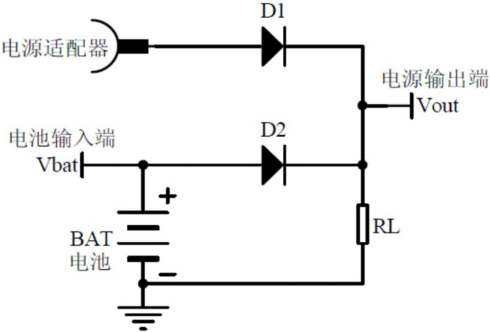
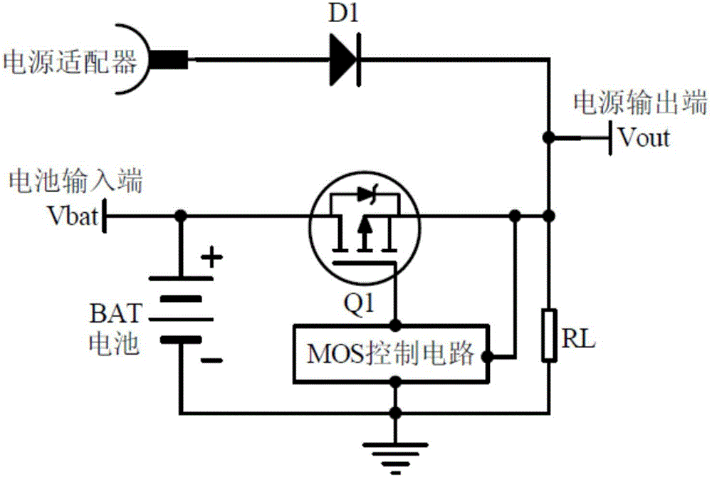
[0037] see figure 1 and figure 2 .

[0038] figure 1 and figure 2 It is a schematic diagram of the circuit structure of a traditional power switching control circuit, which uses the reverse characteristic of the diode to realize the power switching function between the battery BAT and the power adapter. For example: figure 1 When the battery BAT (the input voltage of the battery BAT is represented by Vbat) supplies power to the load RL, the voltage Vout of the load RL terminal is equal to the battery voltage minus the voltage drop of the diode D2 (the ...


PUM


Abstract

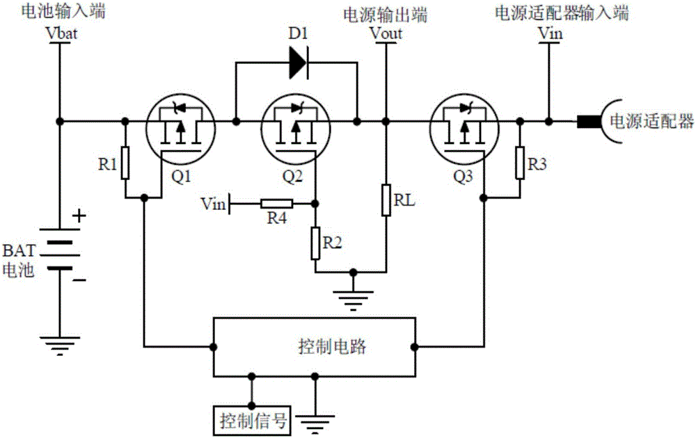
The invention provides a power switching and controlling circuit for controlling a power adapter or battery to supply power to a load. The circuit comprises a switching circuit and a controlling circuit, wherein the switching circuit comprises a first MOS (Metal Oxide Semiconductor) transistor, a second MOS transistor, and a third MOS transistor, and the source of the first MOS transistor is electrically connected with the positive electrode of the battery; the gate of the first MOS tube is electrically connected with the control circuit, and the drain of the first MOS transistor is electrically connected with the drain of the second MOS transistor; the gate of the second MOS transistor is electrically connected with the input terminal of the power adaptor, and the source of the second MOS transistor is electrically connected with a load and then is grounded; the source of the second MOS transistor is also electrically connected with the drain of the third MOS transistor, and the gate of the third MOS transistor is electrically connected with the control circuit; the source of the third MOS transistor is electrically connected with the input terminal of the power adaptor, and the control circuit controls the first MOS transistor and the third MOS transistor to be turned on or off. Compared with the traditional universal power switching and controlling circuit, the power switching and controlling circuit has the advantages of low power consumption, small amount of heat, and high standby efficiency.

Description

technical field [0001] The invention relates to the field of circuit control switching, in particular to a power switching control circuit. Background technique [0002] At present, many portable electronic products are powered by lithium batteries and charged by external power adapters, and can also be used while charging. The traditional lithium battery switching circuit generally uses the reverse characteristic of the diode to switch between the battery and the power adapter. However, due to the large power consumption of the diode itself, it is difficult to meet the needs of today's electronic products with low heat generation, low power consumption during work and standby. directional development needs. Contents of the invention [0003] Based on this, it is necessary to solve the problem that the traditional power switching control circuit is difficult to meet the needs of electronic products in the direction of low heat generation, low working and standby power con...

Claims


Application Information

Patent Timeline
Patent Type & Authority Applications(China)
IPC IPC(8): H02J9/06
CPCH02J9/061Y02B70/30Y04S20/20
Inventor 梁志强
Owner ZHUHAI JIELI TECH
Learn More