Supercharge Your Innovation With Domain-Expert AI Agents!

A permanent magnet direct drive motor for parallel robots and its parallel robot structure

A permanent magnet direct drive and robot technology, applied in the direction of electromechanical devices, manipulators, electrical components, etc., can solve the problems of unreasonable space utilization of parallel robots, uneven force on bearings, and complicated driving devices, etc. The effect of small bearing wear and high control precision

Active Publication Date: 2018-11-13
郑州润华智能设备有限公司 +1
View PDF1 Cites 0 Cited by
  • Summary
  • Abstract
  • Description
  • Claims
  • Application Information

AI Technical Summary

Problems solved by technology

[0004] The purpose of the present invention is to address the defects of the above-mentioned prior art, to provide a permanent magnet direct drive motor for a parallel robot and its parallel robot structure, to overcome the complexity and high price of the existing parallel robot driving device, which requires the cooperation of a reducer and Existing direct drive motors are used in parallel robots, which have the defects of unreasonable space utilization, uneven bearing force, and serious wear and tear.

Method used


Image

  • A permanent magnet direct drive motor for parallel robots and its parallel robot structure
  • A permanent magnet direct drive motor for parallel robots and its parallel robot structure
  • A permanent magnet direct drive motor for parallel robots and its parallel robot structure

Examples


Embodiment Construction

[0025] The following will clearly and completely describe the technical solutions in the embodiments of the present invention with reference to the accompanying drawings in the embodiments of the present invention. Obviously, the described embodiments are only some, not all, embodiments of the present invention. Based on the embodiments of the present invention, all other embodiments obtained by persons of ordinary skill in the art without creative work, any modifications, equivalent replacements, improvements, etc., shall be included in the protection scope of the present invention Inside.

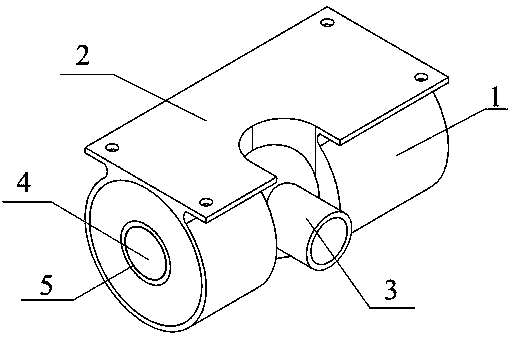
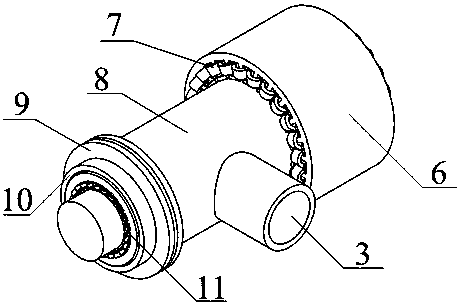
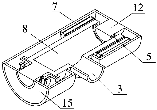
[0026] like Figure 1-4 As shown, the permanent magnet direct drive motor for parallel robots of the present invention includes a rotor 8, a stator that drives the rotor 8 to move, a brake assembly that is included or separated from the rotor and makes the rotor move or remain stationary; the stator It is arranged at one end of the rotor 8, the brake assembly is arranged at the other end...


PUM


Abstract

The invention discloses a permanent magnetic direct drive motor for a parallel robot and a parallel robot structure thereof. The permanent magnetic direct drive motor comprises a rotor, a stator for driving the rotor to be moved, and a brake element for including or separating the rotor and enabling the rotor to be moved or static. The stator is positioned at one end of the rotor, and the brake element is positioned at the other end of the rotor. The middle part of the rotor is vertically provided with an output shaft. The output shaft is positioned in the middle of the stator and the brake element. The parallel robot structure comprises a fixing platform, a driven arm, a knuckle bearing, a medium shaft tube, and a moveable platform. The circumferential part of the fixing platform is fixedly connected with three permanent magnetic direct drive motors. The permanent magnetic direct drive motor for the parallel robot and the parallel robot structure are capable of reducing the volume of the driving device, and reducing the system price. The output shaft of the motor is positioned in the middle of the motor, the space is effectively used, the bearing stress is balanced, and the bearing wear is reduced. The permanent magnetic direct drive motor for the parallel robot and the parallel robot structure have the advantages of the direct drive and high control accuracy and the like.

Description

technical field [0001] The invention relates to a permanent magnet direct drive motor, in particular to a permanent magnet direct drive motor for a parallel robot and the structure of the parallel robot. Background technique [0002] The driving motor used in parallel robots needs the moving axis to drag the active arm to achieve reciprocating motion at a certain angle. The traditional technology uses the cooperation of general motors and reducers to achieve low-speed and high-torque. This solution not only requires many transmission devices, but also the control method Complexity will undoubtedly increase the cost of the robot, and also cause problems such as the size of the robot is too large. However, because the output shaft of the general direct drive motor is located at one end of the motor, when it is applied to a parallel robot, it is easy to cause problems such as unreasonable use of robot space, uneven force on the motor bearing, and serious wear and tear. [0003...

Claims


Application Information

Patent Timeline
Patent Type & Authority Patents(China)
IPC IPC(8): H02K7/102B25J9/12
CPCB25J9/123H02K7/102
Inventor 李应生司纪凯封海潮许孝卓张新良王红旗
Owner 郑州润华智能设备有限公司
Features
  • R&D
  • Intellectual Property
  • Life Sciences
  • Materials
  • Tech Scout
  • Unparalleled Data Quality
  • Higher Quality Content
  • 60% Fewer Hallucinations
Learn More