Detection method and system for E1 link phase jitter
A technology of phase jitter and detection method, which is applied in the field of communication, can solve the problems of expensive phase jitter detection products, and achieve the effect of detection and phase jitter
- Summary
- Abstract
- Description
- Claims
- Application Information
AI Technical Summary
Problems solved by technology
Method used
Image

Examples
Embodiment Construction
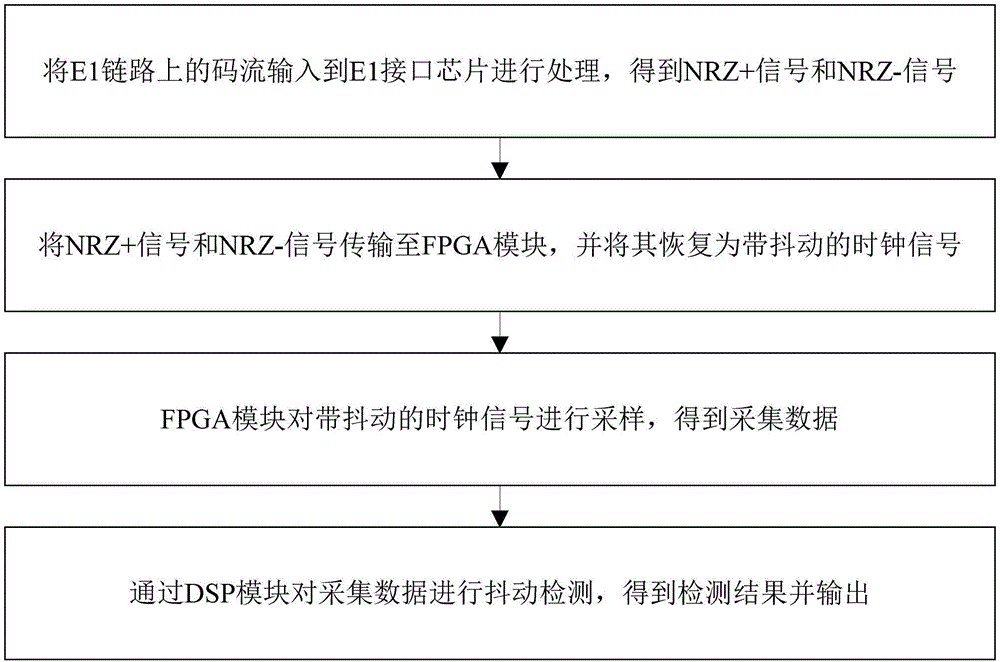
[0048] refer to figure 1 , the detection method of a kind of E1 link phase jitter of the present invention, comprises the following steps:
[0049] Input the code stream on the E1 link to the E1 interface chip for processing to obtain NRZ+ signal and NRZ- signal;
[0050] Transmit the NRZ+ signal and NRZ- signal to the FPGA module and restore it to a clock signal with jitter;
[0051] The FPGA module samples the clock signal with jitter to obtain the collected data;
[0052] The jitter detection is performed on the collected data through the DSP module, and the detection result is obtained and output.
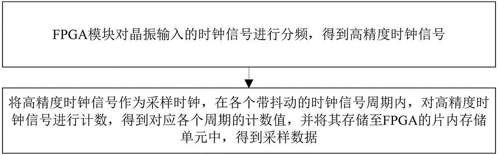
[0053] refer to figure 2 , further as a preferred embodiment, the FPGA module samples the clock signal with jitter to obtain the collected data, and this step includes:
[0054] The FPGA module divides the frequency of the clock signal input by the crystal oscillator to obtain a high-precision clock signal;
[0055] Use the high-precision clock signal as the sampling cloc...
PUM
 Abstract
Description
Claims
Application Information
 - Generate Ideas
- Intellectual Property
- Life Sciences
- Materials
- Tech Scout
- Unparalleled Data Quality
- Higher Quality Content
- 60% Fewer Hallucinations
Browse by: Latest US Patents, China's latest patents, Technical Efficacy Thesaurus, Application Domain, Technology Topic, Popular Technical Reports.
© 2025 PatSnap. All rights reserved.Legal|Privacy policy|Modern Slavery Act Transparency Statement|Sitemap|About US| Contact US: help@patsnap.com