A shadow occlusion detection method for satellite mobile communication

A satellite mobile communication and shadow occlusion technology, which is applied in the field of satellite communication, can solve the problems of inability to judge tree shadows, false judgments, and long time consumption, and achieve the effects of eliminating false judgments and overly sensitive detection judgments, increasing speed, and improving accuracy

Active Publication Date: 2019-01-04
中国人民解放军火箭军工程大学
View PDF5 Cites 0 Cited by
  • Summary
  • Abstract
  • Description
  • Claims
  • Application Information

AI Technical Summary

Problems solved by technology

[0006] 1) "Control Method of Mobile Satellite Tracking Antenna System", (Kia Automobile Co., Ltd., Invention Patent of the People's Republic of China, ZL200310118219.3, 2005), this patent determines whether the antenna pointing is affected by obstacles through the 360-degree rotation of the antenna occlusion, but this method cannot judge the shadow of trees and other situations, and because the antenna needs to be rotated 360 degrees, it takes a long time to judge once
[0007] 2) "Signal Level Detection Dynamic Tracking Satellite Antenna", (Pang Jiangfan, People's Republic of China Use New Patent, ZL200420058643.3, 2006), this patent uses the time derivative of satellite received signal strength to judge whether the antenna is pointing to an occluded object occlusion, but this method cannot effectively judge intermittent occlusion, such as roadside trees, utility poles, etc.
In addition, due to the sensitivity of the gradient, this method will produce a large number of false judgments in practical applications, which lacks practicability
[0008] To sum up, so far, a method for fast and accurate detection of various types of shadow occlusion in satellite mobile communication has not been found

Method used


Image

  • A shadow occlusion detection method for satellite mobile communication
  • A shadow occlusion detection method for satellite mobile communication
  • A shadow occlusion detection method for satellite mobile communication

Examples


Embodiment 1

[0047] In the Xi'an area (latitude 34.16N, longitude 108.54E), use the 0.6m reflector satellite antenna in motion to receive the Asia-Pacific 3S satellite (longitude 105.5°E), and use the beacon receiver to monitor the change of the received signal strength, as shown in the attached Figure 5 shown.

[0048] 1. Characteristic analysis of received signal strength

[0049] According to the change of received signal strength measured before the test, the following three intervals are divided: L 1 =[0,0.5), L 2 =[0.5,3), L 3 =[3,+∞).

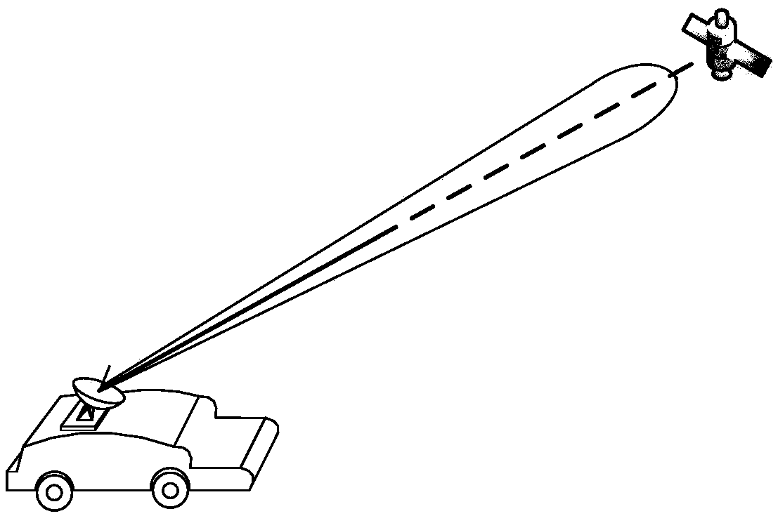
[0050] (1) In an open area, the strength of the signal received by the mobile communication (as shown in the attached Image 6 Shown) mainly jitter within 4.05±0.2V, the signal strength is large, and the change is small. At this time, P 3 = 1, P 1 =P 2 = 0, all signal strengths are at L 3 in the interval;

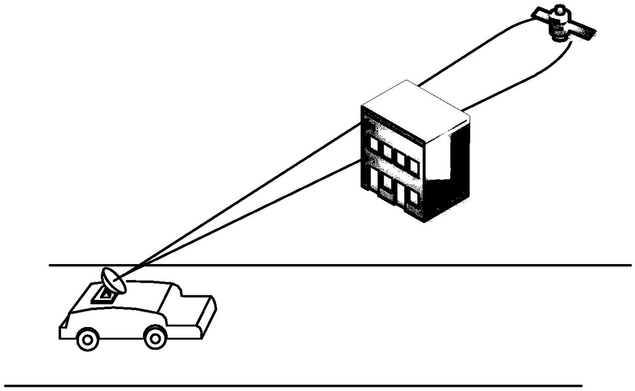
[0051] (2) When driving on roads covered by utility poles and overpasses, the speed of the vehicle is greater than 30km / h, and the rece...


PUM


Abstract

The invention discloses a method for detecting shadow shade in mobile satellite communication. The method comprises the following steps: 1) a satellite communication in motion beam is aligned with a target satellite; 2) when shade is absent and alignment is realized, the maximum strength value M of a receipt signal is counted and analyzed, and then the strength threshold value Tn and Tr of the receipt signal are set; 3) the strength value of the receipt signal acquired at the moment t is Vt; 4) when Vt is smaller than Tn, the target satellite is completely shaded, otherwise, operation turns to step 5); 5) when a carrier of an antenna enters a shade region, a timer is started, the antenna is stopped from tracking the satellite, and orientation of a current beam of the antenna is maintained, when the carrier of the antenna does not enter the shadow shade region, the antenna continues to track the satellite, and the antenna is restarted to track the satellite when the carrier of the antenna travels out of the shadow shade region; when P3 is smaller than or equal to eta, the carrier of the antenna is located in the shadow shade region. With the adoption of the method, whether satellite communication is shaded by a shadow can be detected rapidly and accurately.

Description

technical field [0001] The invention belongs to the technical field of satellite communication, and relates to a shadow blocking detection method for satellite mobile communication. Background technique [0002] In satellite communication in motion, the movement of the carrier will cause the random change of the satellite communication channel environment. The wavelength of electromagnetic waves in the Ku band is only a few centimeters. When the target satellite is blocked by obstacles such as tall buildings on the roadside, billboards, overpasses on the road, and culverts, the communication in motion will not be able to receive the signal, and the satellite communication link will be blocked. broken. Quickly and accurately judging the status of satellite links in motion is an inevitable requirement to ensure reliable communication in motion. [0003] According to the antenna beam width in motion, the obstacle size and the positional relationship between the two, line-of-s...

Claims


Application Information

Patent Timeline
Patent Type & Authority Patents(China)
IPC IPC(8): H04B17/318H04B7/155H04B7/185
CPCH04B7/155H04B7/1853H04B17/318
Inventor 姚敏立袁丁张峰干戴精科郝路瑶王梓涵
Owner 中国人民解放军火箭军工程大学
Why Eureka
Try Eureka