
Automatic continuous quick filtering system

A rapid filtration and automatic technology, applied in the direction of filtration separation, membrane filter, gravity filter, etc., can solve the problems of unrealized continuous filtration and increased blocking force, and achieve low long-term operation cost, small footprint, and saving civil engineering The effect of cost

Inactive Publication Date: 2017-02-01
BROTHER ENVIRONMENTAL PROTECTION EQUIP ENG
View PDF7 Cites 5 Cited by
  • Summary
  • Abstract
  • Description
  • Claims
  • Application Information

AI Technical Summary

Problems solved by technology

[0004] The filter uses granular filter material as the medium. When the raw water passes through the filter layer, the suspended matter is intercepted by the filter layer, and the clean water passes through the filter layer to purify the raw water. After filtering for a period of time, the suspended matter intercepted on the surface of the filter layer increases, resulting in an increase in blocking force. , the filter layer needs to be backwashed. Generally, the filtered water is used as the backwashing water source for the backwashing of the filter. It needs to be equipped with a backwashing water tank and a backwashing water pump. Filtering, backwashing water inlet valve, backwashing water outlet valve, the filtering and backwashing of the filter are realized through the programming of the PLC automatic control system, the defect of this filter is mainly the same as the need to stop the water inlet during backwashing, and continuous filtration is not realized

Method used


Image

  • Automatic continuous quick filtering system
  • Automatic continuous quick filtering system
  • Automatic continuous quick filtering system

Examples


Embodiment Construction

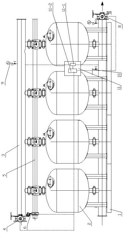
[0032] Such as figure 1 , 2 , 3, and 4, the present invention includes a support base 1 on which four identical filter tanks 2 are installed side by side.

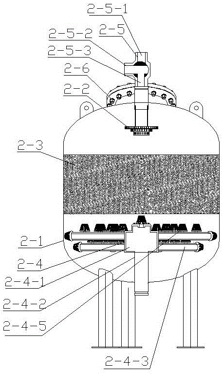
[0033] The filter tank 2 includes a tank body 2-1. A water distributor 2-2, a filter packing layer 2-3 and a water collector 2-4 are sequentially arranged in the tank body 2-1 from top to bottom. The top is provided with a three-way valve 2-5 and a manhole 2-6.

[0034] The three-way valve 2-5 includes a water inlet 2-5-1, a first water outlet 2-5-3 and a second water outlet 2-5-2.

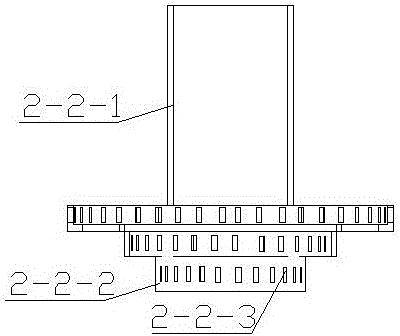
[0035] The water distributor 2-2 includes a water inlet pipe 2-2-1, and the lower end of the water inlet pipe 2-2-1 is connected to three water distribution trays 2-2 which are stacked up and down, have cavities and are connected to each other. -2. The diameters of the three water distribution trays 2-2-2 gradually become smaller from top to bottom, and the side walls of the water distribution trays 2-2-2 are evenly distributed with water d...


PUM


Abstract

The invention discloses an automatic continuous quick filtering system and relates to the field of filtering equipment. The automatic continuous quick filtering system comprises a plurality of same filtering tanks and a control device, wherein each filtering tank comprise a tank body; a water distributor, a filtering filler layer and a water collector are sequentially arranged in each tank body from top to bottom; a three-way valve is arranged at the top of each tank body; each three-way valve comprises a water inlet, a first water outlet and a second water outlet; the first water outlet of each three-way valve is connected with a water inlet of each water distributor; the outlet end of each water collector outward extends out of the corresponding filtering tank; the water inlets of the three-way valves are connected by a water inlet manifold to form a whole; the second water outlets of the three-way valves are connected by a backwash water outlet manifold to form a whole; the outlet ends of the water collectors are connected by a water outlet manifold to form a whole. According to the automatic continuous quick filtering system disclosed by the invention, a backwash process and a filtering process are simultaneously performed, and the system usually supplies water; by adopting unique water distributors and water collectors, water flow becomes laminar flow in the whole filtering process, and the quality of effluent is stable.

Description

technical field [0001] The invention relates to the field of filtering equipment, in particular to an automatic continuous rapid filtering system. Background technique [0002] In the process of working water, surface water, agricultural irrigation, aquaculture and circulating water, it is necessary to remove suspended matter in the water through a filter. [0003] The traditional filter uses main pipes and branch pipes to distribute water through water distribution holes or wedge-shaped filter pipes. The filter layer is supported on the filter plate, and the filter plate is equipped with a filter head. After collecting water through the filter head, it is discharged from the tank through the outlet pipe. body. Considering that the transportation generally uses multiple filters in parallel for large water volumes, and generally uses one filter for small water volumes [0004] The filter uses granular filter material as the medium. When the raw water passes through the filt...

Claims


Application Information

Patent Timeline
IPC IPC(8): B01D24/00B01D24/14B01D24/40B01D24/42B01D24/46B01D24/48
CPCB01D24/007B01D24/14B01D24/402B01D24/425B01D24/4642B01D24/48B01D2101/04B01D2201/086B01D2201/16B01D2201/54
Inventor 于德顺
Owner BROTHER ENVIRONMENTAL PROTECTION EQUIP ENG
Learn More