
A purification device for exhaust gas containing oil mist

A purification device and exhaust gas technology, applied in gas treatment, chemical instruments and methods, separation methods, etc., can solve the problems of short service life of filter materials, frequent replacement, high cleaning costs, etc., increase the gas-liquid contact area, and facilitate removal and cleaning , The effect of improving the purification efficiency

Active Publication Date: 2019-04-26
AEROSPACE KAITIAN ENVIRONMENTAL TECH CO LTD
View PDF9 Cites 0 Cited by
  • Summary
  • Abstract
  • Description
  • Claims
  • Application Information

AI Technical Summary

Problems solved by technology

However, mechanical oil mist purifiers often have a short service life of the filter material and frequent replacement. Some oil mist purifiers that can be backwashed have appeared in the prior art, but they consume a lot of energy and are expensive, and the viscosity of the oil mist makes them Easy to stick to the impeller
[0005] The working principle of electrostatic oil mist purification technology is to use the strong electric field of high-voltage static electricity to charge the oil mist particles, and the charged particles reach the electrode and be adsorbed by the adsorption electrode. The filtering effect is limited, and the cleaning cost is high, which increases maintenance and operation costs, and its application is limited
[0006] Moreover, the conventional oil mist purification is only aimed at the oil mist generated in the machining industry, and does not treat the accompanying exhaust gas

Method used


Image

  • A purification device for exhaust gas containing oil mist
  • A purification device for exhaust gas containing oil mist
  • A purification device for exhaust gas containing oil mist

Examples


Embodiment

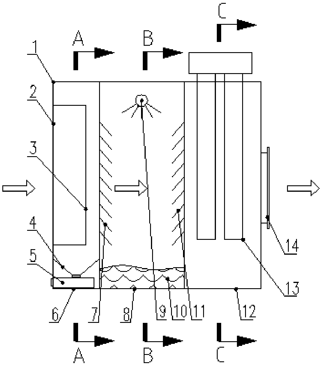
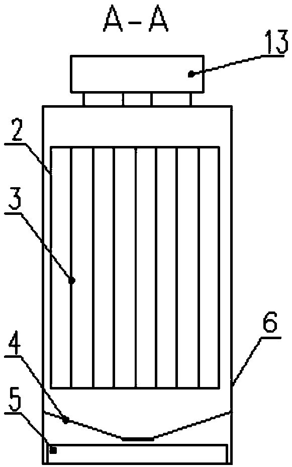
[0039] see Figure 1 to Figure 5 , the purification device for oil mist exhaust gas in the illustration is a preferred embodiment of the present invention, specifically including an outer shell 1, an air inlet 2, an organ-type oil baffle 3, an oil bucket 4, an oil tank 5, and an oil mist recovery section box 6 , inlet baffle 7, micro-bubble purification section box 8, micro-bubble generator 9, circulating fluid 10, outlet baffle 11, high-energy ion purification section box 12, high-energy ion purifier 13, air outlet 14, water inlet pipe 15 , circulating water pump 16 and outlet pipe 17 and other components.

[0040] Specifically, the purification device of this embodiment mainly includes three parts, which are sequentially connected in series: an oil mist recovery section, a microbubble purification section, and a high-energy ion purification section. In the body 8 and the high-energy ion purification section box 12, the oil mist recovery section box 6, the microbubble purifi...


PUM


Abstract

The invention discloses a purification device for oil mist-containing waste gas. The purification device comprises an oil mist recovery segment, a micro bubble purification segment and a high energy ion purification segment which are sequentially connected in series with one another; an air inlet is formed in the oil mist recovery segment and is provided with an oil baffle plate; an oil groove used for recovering oil liquid is formed in the bottom of the oil baffle plate; an inlet and an outlet which communicate with the oil mist recovery segment and the high energy ion purification segment respectively are formed in the micro bubble purification segment; a micro bubble generator is arranged between the inlet and the outlet and is connected with a micro bubble circulating liquid system; an air outlet is formed in the high energy ion purification segment; and a high energy ion purifier is arranged in front of the air outlet. The purification device integrates oil mist removal and waste gas purification, has a compact structure, is high in purification efficiency, can be widely applied to treating the oil mist-containing waste gas and recovers and reuses the oil mist so as to improve the working environment of a worker and also effectively maintain physical and psychological health of an operator.

Description

technical field [0001] The invention belongs to the field of purification of oil mist and industrial waste gas, and in particular relates to a purification device for waste gas containing oil mist. Background technique [0002] In the machining industry, due to the wide use of cutting fluid, the processing workshop is full of exhaust gas containing oil mist, which poses safety hazards, pollutes the production environment and endangers the physical and mental health of the human body. In order to effectively protect the environment and maintain human health, oil mist purification or recovery devices are often added to processing machines to reduce the adverse effects of oil mist on the working environment and to recycle the oil in the oil mist. [0003] At present, the commonly used oil mist purification methods mainly include mechanical and electrostatic methods. [0004] The common mechanical type is to use the principle of physical interception, directly intercept by filt...

Claims


Application Information

Patent Timeline
Patent Type & Authority Patents(China)
IPC IPC(8): B01D45/08B01D53/74
CPCB01D45/08B01D53/74B01D2258/02B01D2259/818
Inventor 彭芬
Owner AEROSPACE KAITIAN ENVIRONMENTAL TECH CO LTD
Learn More