
Turning method for thin and long threaded shaft

A threaded shaft and slender technology, which is applied in the field of turning slender threaded shafts, can solve problems such as difficult clamping of workpieces, irregular thread tooth profiles, and unstable thread cutting, etc., to achieve fast and convenient operation, ensure processing quality, reduce deformation effect

Active Publication Date: 2017-02-01
嘉兴大力精密紧固件股份有限公司
View PDF5 Cites 2 Cited by
  • Summary
  • Abstract
  • Description
  • Claims
  • Application Information

AI Technical Summary

Problems solved by technology

[0002] For threads with small nominal diameter, long processing length and poor workpiece rigidity, it is difficult to clamp the workpiece during processing, the thread cutting is not stable, and the workpiece is difficult to maintain a stable state, etc., resulting in bending deformation of the axis of the external thread of the slender rod and irregular thread profile. , chaotic teeth and other problems, the material of the external threaded part of the slender rod has good plasticity and toughness, but poor hardness
In addition, if the threaded part is located in the middle of the slender shaft, due to the small diameter and poor rigidity of the workpiece, a large deformation will occur during the cutting process and the machining cannot continue

Method used


Image

  • Turning method for thin and long threaded shaft
  • Turning method for thin and long threaded shaft
  • Turning method for thin and long threaded shaft

Examples


Embodiment Construction

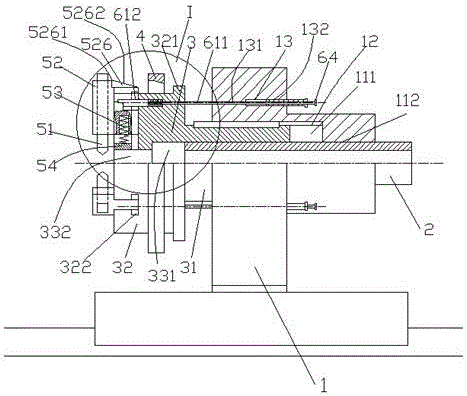
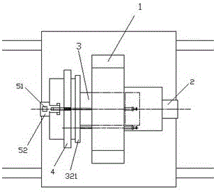
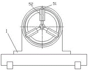
[0029] A device for turning an elongated threaded shaft on a lathe, which uses a device for turning an elongated threaded shaft, the device for turning an elongated threaded shaft is installed on a large carriage of a lathe, which includes a base 1, Guide sleeve 2, telescopic sleeve 3, tool reset ring 4, thread length control mechanism and tool assembly;

[0030] The base 1 is installed on the large carriage of the lathe, and a cylinder is arranged on the right side of the base 1, and three uniformly distributed light holes 131 and diameters suddenly become larger and are provided with an inner cylinder around the cylinder. The first step hole 13 formed by threaded deep holes 132, the middle part of the base 1 is provided with a second step hole consisting of a hole A111 with a larger diameter and a hole B112 with a smaller diameter on the cylinder, and the hole A111 is set There is a long groove 12 with a rectangular cross-section in the left and right directions;

[0031] T...


PUM


Abstract

The invention discloses a turning method for a thin and long threaded shaft. A turning device for the thin and long threaded shaft is used in the method and is installed on a carriage of a lathe. The turning device comprises a base, a guiding sleeve, a telescopic sleeve, a tool reset ring, a thread length control mechanism and a tool assembly. The turning device has the beneficial effects that due to the fact that scale marks are arranged on the surface of the outer circle of the part, close to a shaft ring, of the thin and long shaft, the length value of a to-be-turned thread can be accurately adjusted by adjusting the axial position of a screw sleeve; due to the fact that three sets of turning tools are distributed evenly in the circumferential direction, deformation of the threaded shaft in the turning process is reduced, and the machining quality is ensured; due to the fact that a slope A and a slope C which can be in contact or be separated are arranged, ending machining of the thread can be accurately achieved, and the phenomenon of tool crashing is effectively avoided; and due to the fact that the tool reset ring is arranged, the three sets of turning tools can contract towards the center at the same time, and operation is fast and convenient.

Description

technical field [0001] The invention relates to the technical field of mechanical processing, in particular to a turning method of an elongated threaded shaft. Background technique [0002] For threads with small nominal diameter, long processing length and poor workpiece rigidity, it is difficult to clamp the workpiece during processing, the thread cutting is not stable, and the workpiece is difficult to maintain a stable state, etc., resulting in bending deformation of the axis of the external thread of the slender rod and irregular thread profile. , disordered teeth and other problems, the material of the external threaded part of the slender rod has good plasticity and toughness, but poor hardness. In addition, if the threaded part is located in the middle of the slender shaft, due to the small diameter and poor rigidity of the workpiece, a large deformation will occur during the cutting process and the machining cannot continue. Contents of the invention [0003] The...

Claims


Application Information

Patent Timeline
Patent Type & Authority Applications(China)
IPC IPC(8): B23G1/04B23G1/44B23G1/46B23G1/48B23G11/00
CPCB23G1/04B23G1/44B23G1/46B23G1/48B23G11/00
Inventor 周晓飞
Owner 嘉兴大力精密紧固件股份有限公司
Learn More