Large-array surface phased array radar antenna

A phased array radar and antenna technology, which is applied to antennas, antenna arrays, antenna arrays that are powered independently, etc., can solve the problems of high cost and high innovation cost, and achieve the effects of small quantity, reduced connection work, and reduced transmission and reception loss

Inactive Publication Date: 2017-02-01
ANHUI SUN CREATE ELECTRONICS
View PDF0 Cites 10 Cited by
  • Summary
  • Abstract
  • Description
  • Claims
  • Application Information

AI Technical Summary

Problems solved by technology

In order to reduce the high cost caused by the excessive number of T/R components, most of them currently use low-temperature co-fired ceramic (LTCC) multilayer interconnect packaging technology, radio frequency chip-scale integration (RF-WSI) technology or GaAs MMIC Flip-ch

Method used


Image

  • Large-array surface phased array radar antenna
  • Large-array surface phased array radar antenna
  • Large-array surface phased array radar antenna

Examples


Embodiment Construction

[0039] For ease of understanding, the specific implementation structure and workflow of the present invention are described below in conjunction with the accompanying drawings:

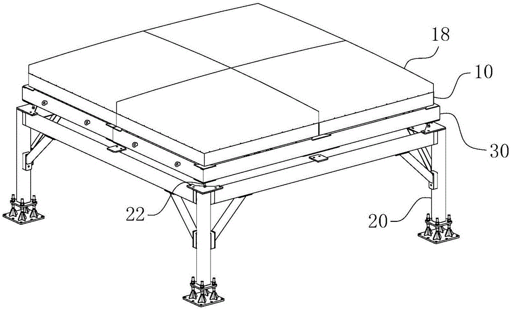
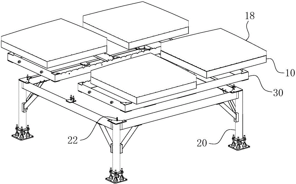
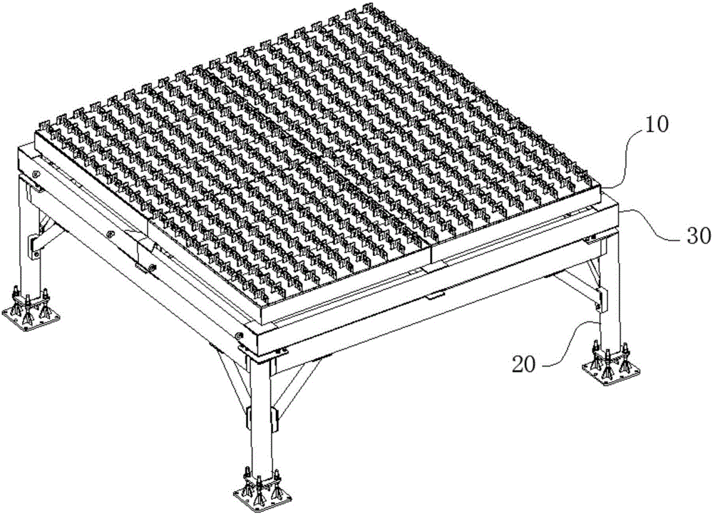
[0040] The concrete implementation structure of the present invention, as Figure 1-13As shown, it includes four sets of array antennas 10 , two sub-skeletons 30 and a set of support frames 20 arranged sequentially from top to bottom. The four array antennas 10 are fixed to the upper surfaces of the two sub-frames 30 in pairs according to a certain order, and then the two sub-frames 30 are installed on the upper surface of the supporting frame 20 . The support frame 20 is provided with a two-stage leveling structure formed by fixing bolts 22 and an additional adjusting screw 21c, so as to ensure the flatness requirements of the assembled antenna array. Such as Figure 1-3 As shown, after the assembly of the four groups of array antennas 10 of the present invention is completed, a large array antenna...


PUM


Abstract

The invention belongs to the technical field of radar electronics, in particular relates to a large-array surface phased array radar antenna. The large-array surface phased array radar antenna comprises an array surface antenna and a support rack, wherein the array surface antenna comprises antenna line oscillators and antenna row oscillators, the number of the antenna row oscillators is equal to the number of the antenna line oscillators, the distance between two adjacent groups of antenna line oscillators is equal to the distance between two adjacent groups of antenna row oscillators, each antenna line oscillator and each antenna row oscillator cross to form a cross meshed structure of the array surface antenna, top end surfaces of dipoles after each antenna line oscillator and each antenna row oscillator cross are arranged on the same plane, symmetric surfaces of two adjacent dipoles on each group of antenna line oscillator are arranged on a plane where the group of antenna line oscillators are located, and the symmetric surface of each dipole on each group of line oscillators is arranged on a plane where the group of antenna row oscillators are located. By the large-array surface phased array radar antenna, the usage quantity of T/R modules can be effectively reduced on the premise that the working accuracy of the radar antenna can be ensured, and the purpose of effectively controlling cost is further achieved.

Description

technical field [0001] The invention belongs to the technical field of radar electronics, and in particular relates to a large array phased array radar antenna. Background technique [0002] The transmit / receive component on the phased array radar front, also known as the T / R component, is one of the core components of the radar. With the continuous development of phased array radar technology, the requirements for T / R components are getting higher and higher, and the number of T / R components required by large radars is also increasing. In order to reduce the high cost caused by the excessive number of T / R components, most of them currently use low-temperature co-fired ceramic (LTCC) multilayer interconnect packaging technology, radio frequency chip-scale integration (RF-WSI) technology or GaAs MMIC Flip-chip design and integration technology can be used to solve the problem; since the above-mentioned technologies all seek improvement from the T / R component itself, the cost...

Claims


Application Information

Patent Timeline
IPC IPC(8): H01Q21/06H01Q3/34H01Q3/04
CPCH01Q21/062H01Q3/04H01Q3/34
Inventor 陈常明李德威孙浩陆地
Owner ANHUI SUN CREATE ELECTRONICS
Why Eureka
Try Eureka