Panel of permanent magnetic chuck

A permanent magnetic chuck and panel technology, which is applied in the direction of workpiece clamping devices, manufacturing tools, etc., can solve the problems affecting the performance and service life of the panel, water and other liquid leakage, and the displacement of the magnetic sheet, so as to achieve good structural stability High performance, improved service life and working stability, strong magnetic conduction and adsorption capacity

Active Publication Date: 2017-02-08
宁波大生磁电科技有限公司
View PDF5 Cites 0 Cited by
  • Summary
  • Abstract
  • Description
  • Claims
  • Application Information

AI Technical Summary

Problems solved by technology

[0004] The suction cup panel is generally formed by arranging and stacking the magnetic guide sheet and the magnetic isolation sheet at intervals, and then fixing the magnetic guide sheet and the magnetic isolation sheet with a locking mechanism. Each component structure has a small movable space in the panel. Especially between the magnetic conductive sheet and the magnetic isolation sheet, due to the different magnetic adsorption force under the working / non-working state, it will be displaced or deformed due to the change of the magnetic force on the magnetic conductive sheet, which will aggravate the wear between the two
In addition, because the magnetic force received by the magnetic sheet is slightly shifted towards the direction of the magnetic source in the working state, the non-uniform contact between the panel and the adsorbed workpiece will cause non-uniform wear, and leakage of water and other liquids will easily occur during use. , which affects the performance and service life of the panel

Method used


Image

  • Panel of permanent magnetic chuck

Examples


Embodiment 1

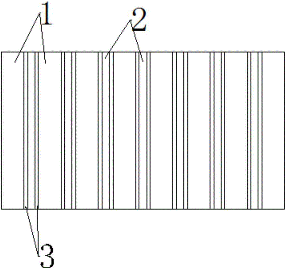
[0028] In this embodiment, the permanent magnetic chuck panel includes a main body, which at least has the function of conducting a magnetic field: the main body includes a magnetic flux unit and a boundary unit with magnetic flux properties, and the magnetic flux unit and the boundary unit are all in the form of a layer, and the magnetic The flux unit and the boundary unit are stacked in a side-by-side parallel state, wherein each magnetic flux unit includes at least one magnetic flux member (that is, one or two or three or four or more magnetic flux members are laminated or combined The form of the magnetic flux unit is formed. In this scheme, the number of magnetic flux pieces selected in each magnetic flux unit in the panel can be the same or different. The number of magnetic flux pieces in each magnetic flux unit can include but not limited to the aforementioned scheme any of the).

Embodiment 2

[0030] In this embodiment, the permanent magnetic chuck panel includes a main body, which at least has the function of conducting a magnetic field: the main body includes a magnetic flux unit and a boundary unit with magnetic flux properties, and the magnetic flux unit and the boundary unit are all in the form of a layer, and the magnetic The communication unit and the boundary unit are stacked side by side in a parallel state, wherein each boundary unit includes at least one boundary piece (that is, one or two or three or four or more boundary pieces are formed by stacking or combining Boundary units, in this solution, the number of boundary pieces selected in each boundary unit in the panel may be the same or different, and the number of boundary pieces in each boundary unit may include but not limited to any of the aforementioned schemes).

Embodiment 3

[0032] In this embodiment, the permanent magnetic chuck panel includes a main body, which at least has the function of conducting a magnetic field: the main body includes a magnetic flux unit and a boundary unit with magnetic flux properties, and the magnetic flux unit and the boundary unit are all in the form of a layer, and the magnetic The flux unit and the boundary unit are stacked in a side-by-side parallel state, and each magnetic flux unit includes at least one magnetic flux member (that is, one or two or three or four or more magnetic flux members are stacked or combined. form the magnetic flux unit, in this scheme, the number of magnetic flux pieces selected in each magnetic flux unit in the panel can be the same or different, and the number of magnetic flux pieces in each magnetic flux unit can be included but not limited to the aforementioned scheme Any one of) and each boundary unit includes at least one boundary piece (that is, one or two or three or four or more b...


PUM


Abstract

The invention discloses a panel of a permanent magnetic chuck. The panel comprises a main body, wherein the main body at least has the effect of conducting a magnetic field and at least comprises magnetic flux units having magnetic flux performance and dividing units; the magnetic flux units and the dividing units are lamellar and are stacked in parallel; and each magnetic flux unit at least comprises one magnetic flux piece and/or each dividing unit at least comprises one dividing piece. The panel of the chuck has the good magnetic flux performance, has the high magnetic conduction and adsorption capacity and the low magnetic field attenuation in the working state and has the good structural stability, the high waterproofness and the good adaptability to an application environment, the service life of the chuck is prolonged, and the working stability of the chuck is improved.

Description

technical field [0001] The invention relates to a magnetic chuck device, in particular to a permanent magnetic chuck panel. Background technique [0002] Permanent magnetic chuck, also known as magnetic chuck, is a magnetic fixture widely used in machinery factories, mold factories, and other machining fields, which can greatly improve the clamping efficiency of magnetic steel materials. The permanent magnetic chuck is based on the high-performance rare earth material NdFeB (N>40), and the magnetic system of the NdFeB inside the chuck can be changed by turning the handle of the suction cup by hand to achieve the holding or releasing of the workpiece to be processed. The permanent magnetic chuck is designed by using the principle of continuity of magnetic flux and the principle of superposition of magnetic field. The magnetic circuit of the permanent magnetic chuck is designed into multiple magnetic systems. Elimination, so as to achieve the purpose of holding and unloadi...

Claims


Application Information

Patent Timeline
Patent Type & Authority Applications(China)
IPC IPC(8): B25B11/00
CPCB25B11/002
Inventor 水成明
Owner 宁波大生磁电科技有限公司
Why Eureka
Try Eureka