
Method and system for confirming non-Newtonian fluid injection speed in laboratory experiment

A non-Newtonian fluid and injection velocity technology, applied in the field of oilfield development laboratory experiments, can solve the problems of convincing limitations of results, influence of oil displacement effect evaluation, single determination method of injection velocity, etc.

Active Publication Date: 2017-02-08
CHINA NAT OFFSHORE OIL CORP +1
View PDF9 Cites 4 Cited by
  • Summary
  • Abstract
  • Description
  • Claims
  • Application Information

AI Technical Summary

Problems solved by technology

However, when this method determines the relationship curve between capillary number and residual oil saturation, the experimental liquid injection rate is only based on the seepage velocity at the main line of the high-permeability layer of the oil flooding site where the driving state transition is likely to occur, and does not take into account The radial flow to the fluid and the curved flow in the actual reservoir pores will affect the accuracy of the experimental results
[0005] Therefore, the defect in the prior art is that when the artificial simulated rock core is displaced by the non-Newtonian fluid in the existing laboratory experiment, the method for determining the injection velocity is single, because it is not combined with the fluid flow pattern on site, so that the injection velocity value There is a certain deviation in the size of , which will eventually affect the evaluation of the oil displacement effect, and the convincing results of the existing laboratory experiments for oil displacement have certain limitations.

Method used


Image

  • Method and system for confirming non-Newtonian fluid injection speed in laboratory experiment
  • Method and system for confirming non-Newtonian fluid injection speed in laboratory experiment
  • Method and system for confirming non-Newtonian fluid injection speed in laboratory experiment

Examples


Embodiment 1

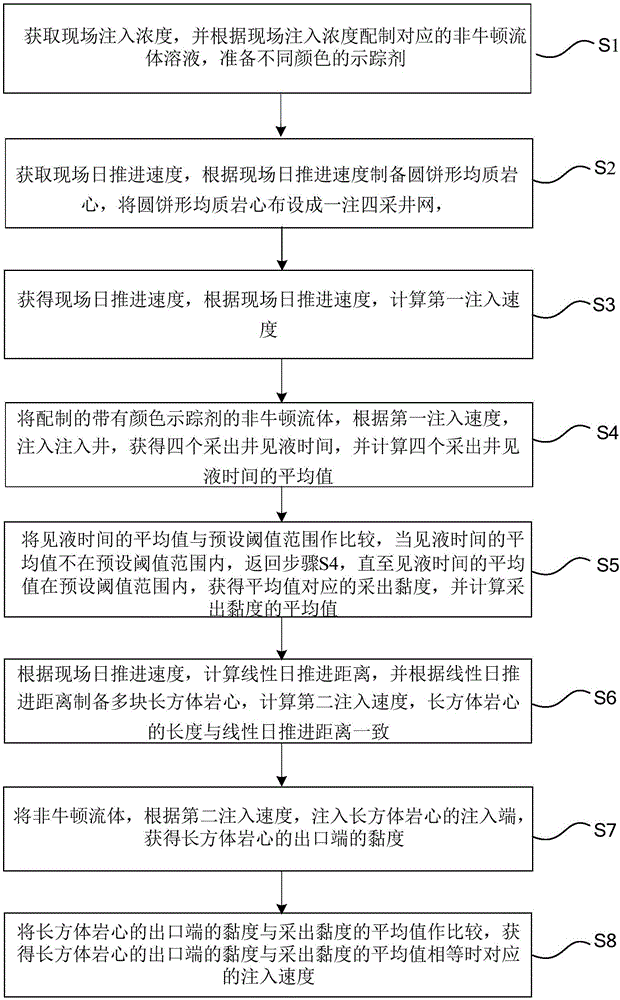
[0077] figure 1 A flow chart of a method for determining the injection velocity of a non-Newtonian fluid in an indoor experiment provided by the first embodiment of the present invention is shown. Such as figure 1 As shown, the method for determining the injection velocity of the non-Newtonian fluid in the indoor experiment according to the first embodiment of the present invention includes:

[0078] Step S1, obtain the on-site injection concentration, prepare the corresponding non-Newtonian fluid solution according to the on-site injection concentration, and prepare tracers of different colors;

[0079] Step S2, obtain the site’s daily advancing speed, prepare circular cake-shaped homogeneous cores according to the site’s daily advancing speed, and arrange the circular cake-shaped homogeneous cores into a one-injection and four-production well pattern, which consists of one injection well and four production wells. Composition of production wells, injection wells are arrang...

Embodiment 2

[0111] figure 2 A schematic diagram of a system for determining the injection velocity of a non-Newtonian fluid in an indoor experiment provided by the second embodiment of the present invention is shown. Such as figure 2 As shown, the indoor experiment non-Newtonian fluid injection velocity determination system 10 according to the second embodiment of the present invention includes:

[0112] The experimental solution preparation module 101 is used to obtain the on-site injection concentration, prepare the corresponding non-Newtonian fluid solution according to the on-site injection concentration, and prepare tracers of different colors;

[0113] The circular pie-shaped homogeneous core preparation module 102 is used to obtain the on-site daily advance speed, prepare the circular cake-shaped homogeneous core according to the on-site daily advance speed, and arrange the circular cake-shaped homogeneous core into a well network with one injection and four productions, one inj...

Embodiment 3

[0145]In view of the fact that the injection-production wells in the polymer flooding block of Daqing Oilfield advance 1 meter per day, the indoor experimental injection rate is determined, and the method and system for determining the indoor experimental non-Newtonian fluid injection rate of the present invention are described in detail in combination with the specific indoor experimental conditions and experimental data. illustrate.

[0146] 1. Prepare a polymer solution with a concentration of 1000mg / L, and prepare tracers of 7 colors, which are red, yellow, blue, green, pink, brown, and orange. These tracers have no effect on the viscosity of the polymer solution. obvious impact;

[0147] 2. Prepare circular cake-shaped cast rock cores and cuboid cast rock cores for simulation experiments;

[0148] 1), preparing a round cake-shaped light slab core 6 and casting;

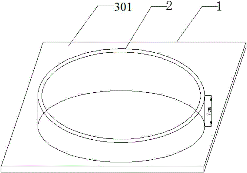
[0149] Advance 1 meter every day on the spot, then the radius 1m of the prepared round cake shape light slab...


PUM

PropertyMeasurementUnit
Diameteraaaaaaaaaa
Thicknessaaaaaaaaaa
Pore volumeaaaaaaaaaa

Abstract

The invention discloses a method and a system for confirming a non-Newtonian fluid injection speed in laboratory experiment. The method comprises the following steps of: preparing a non-Newtonian fluid solution according to an on-site injection concentration, preparing tracer agents of different colors, preparing a cake-shaped homogenous rock core according to an on-site daily advance speed, adding the non-Newtonian fluid solution into the tracer agents, injecting into an injection well of the cake-shaped homogenous rock core at a first injection speed till the average value of a liquid seeing time is within a preset threshold range, and calculating the average value of extraction viscosities; and according to the on-site daily advance speed, preparing a plurality of rectangular rock cores, injecting the non-Newtonian fluid solution into injection ends of the rectangular rock cores at a second injection speed, acquiring viscosities of outlet ends of the rectangular rock cores, and testing corresponding injection speeds when the viscosities of the outlet ends are equal to the average value of the extraction viscosities. According to the method and the system for confirming the non-Newtonian fluid injection speed in laboratory experiment, the cake-shaped homogenous rock core and the rectangular rock cores are adopted to test, the injection speed can be confirmed, and the result of conventional oil-expelling laboratory experiment can be relatively accurate.

Description

technical field [0001] The invention relates to the field of indoor experiments for oil field development, in particular to a method and system for determining the injection velocity of non-Newtonian fluids in indoor experiments. Background technique [0002] At present, most of the old oilfields have entered the period of high water cut and ultra-high water cut. After water flooding, chemical flooding such as polymer flooding, binary flooding, and three-element flooding has gradually become a new method to enhance oil recovery. On-site non-Newtonian fluid systems, including polymer solutions, binary solutions, ternary solutions and other non-Newtonian fluids, are injected with the injection well as the center, and the fluid flows radially, with different flow velocities at different locations. [0003] However, the current indoor simulation can only take the linear velocity of a section between a single injection well and the production well for simulation. For example, the...

Claims


Application Information

Patent Timeline
IPC IPC(8): G01N33/24
CPCG01N33/24
Inventor 刘丽皮彦夫李静刘斌
Owner CHINA NAT OFFSHORE OIL CORP
Learn More