A fault range identification device and identification method for an intelligent area backup automatic switching system

A technology of fault range and identification method, which is applied in the field of electric power, can solve the problems of power grid secondary impact power outage range, expansion, and closing on faults, etc., and achieve the effects of low dependence, reduced dependence, and simplified configuration

Active Publication Date: 2019-02-15
CENT SOUTHERN CHINA ELECTRIC POWER DESIGN INST CHINA POWER ENG CONSULTING GROUP CORP +1
View PDF6 Cites 0 Cited by
  • Summary
  • Abstract
  • Description
  • Claims
  • Application Information

AI Technical Summary

Problems solved by technology

[0009] It solves the problem that due to the variety of main wiring forms and simplified relay protection configuration in the 110kV and below power grids, when there is no busbar protection or protection overstepping trips, the regional standby automatic switching system using the existing technology is due to the bus differential protection and main transformer backup. If the protection action signal is used to block the standby automatic switching device, there will be a risk that the standby automatic switching will be closed in a fault, resulting in technical problems such as secondary impact on the power grid and even expansion of the power outage range.

Method used


Image

  • A fault range identification device and identification method for an intelligent area backup automatic switching system
  • A fault range identification device and identification method for an intelligent area backup automatic switching system
  • A fault range identification device and identification method for an intelligent area backup automatic switching system

Examples


Embodiment Construction

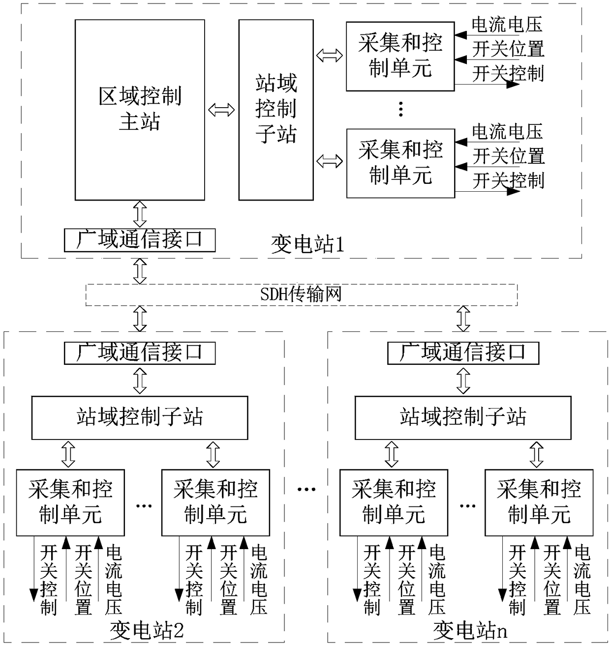
[0048] A fault range identification device for an intelligent regional standby automatic switching system, which includes a station domain control sub-station and a regional control master station, collecting and controlling

[0049] The unit is connected with the station domain control substation, and the station domain control substation is connected with the area control master station.

[0050] The station domain control sub-station is connected with the regional control master station through the SDH transmission network.

[0051] The collection and control unit collects corresponding switch position and current and voltage information, and has a switch control function.

[0052] The device of the present invention is based on real-time information, adopts a hierarchical distributed structure, sets a control master station and multiple control sub-stations, and has the functions of coordinated control and station domain control, and the master station and each sub-station...


PUM


Abstract

The invention discloses a fault range identification device and identification method for an intelligent regional spare power automatic switching system. The fault range identification device comprises station domain control sub-stations and a regional control master station; acquisition and control units are connected with the station domain control sub-stations; and the station domain control sub-stations are connected with the regional control master station. The identification method includes the following steps that: a switch trip event in a regional spare power automatic switching real-time detection area is detected, whether a voltage loss area is formed is judged, a power source circuit breaker corresponding to the voltage loss area is identified; the station domain control sub-stations of the regional spare power automatic switching system detect the direction of fault current of local measurement points; obtained results are uploaded to the regional control master station in real time, the regional control master station collects the real-time information of all measurement points in the area; and the regional control master station carries out fault range identification according to the identified voltage loss area and synchronous fault current direction marks of related measurement points. With the identification device and identification method adopted, technical problems such as the problem of a large risk that a regional spare power automatic switching system is switched on under a fault in the prior art when a power grid does not have bus-bar protection or protection override trip occurs can be solved.

Description

technical field [0001] The invention belongs to the field of electric power technology, and in particular relates to a fault range identification device and identification method of an intelligent area backup automatic switching system. Background technique [0002] Backup power self-injection devices have been widely used in power systems, which can not only improve the reliability of grid power supply, but also simplify grid operation and limit short-circuit current. There is a close cooperation relationship between standby automatic switching and relay protection. When the grid fault trips and loses voltage, the standby automatic switching device needs to judge whether the fault point is located on the side of the voltage-loss bus. If so, it should block the standby automatic switching to prevent the standby power supply from closing on the fault, causing the grid to be subjected to secondary impacts or even expanding the scope of power outages. [0003] At present, in t...

Claims


Application Information

Patent Timeline
Patent Type & Authority Patents(China)
IPC IPC(8): H02H7/26H02H7/22H02J9/06
CPCH02H7/22H02H7/26H02J9/061H02J9/068
Inventor 颜俊张立平田雨安小波代运滔杨令王杰董睿智何维李刚马静赵峻马怡晴饶志
Owner CENT SOUTHERN CHINA ELECTRIC POWER DESIGN INST CHINA POWER ENG CONSULTING GROUP CORP
Why Eureka
Try Eureka