Reversible overflow gate device for large grit chamber
A technology of overflow gate and grit chamber, which is applied to the feeding/discharging device of the sedimentation tank, etc., can solve the problems of inability to separate sand and water, occupy a large space, add water for dilution, etc., and reduce the number of sand and water separation equipment. , the effect of small footprint
- Summary
- Abstract
- Description
- Claims
- Application Information
AI Technical Summary
Problems solved by technology
Method used
Image

Examples
Embodiment Construction
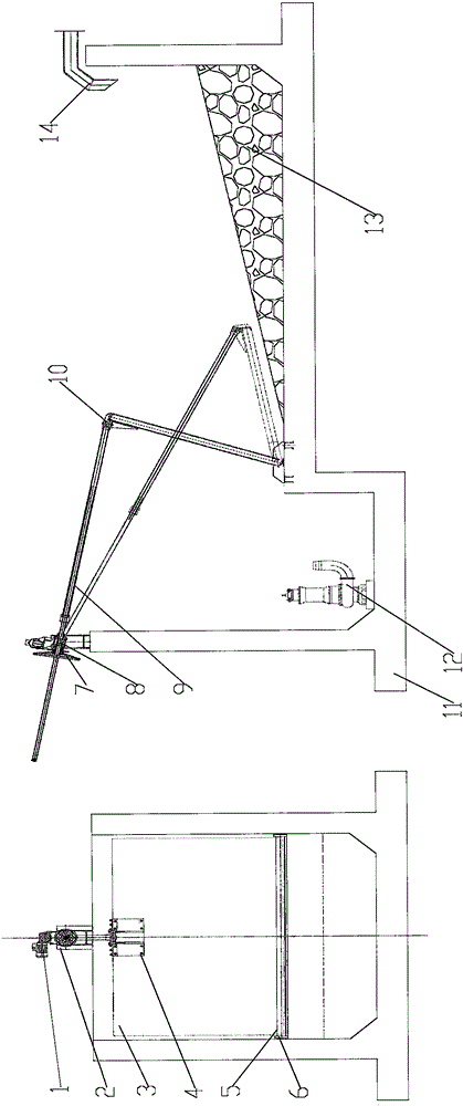
[0016] The specific implementation manners involved in the present invention will be described below in conjunction with the accompanying drawings.
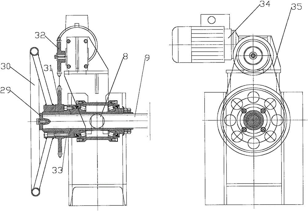
[0017] The height of the top of the overflow ram 3 is adjusted manually and electrically. During the commissioning stage and when materials with different sand contents are injected into the grit chamber 11, the height of the top of the overflow ram 3 is manually adjusted. When the sand settling process parameters are determined In the future, the height of the top of the overflow gate 3 will be automatically adjusted in an electric manner. The difference between the manual and electric modes of adjustment is: manual means to manually rotate the hand wheel 30, the hand wheel 30 drives the shaft sleeve 33 to rotate through the key, and the electric means that the reduction motor drives the shaft sleeve 33 to rotate through the key through the sprocket chain, etc., and the connecting rod 9 The end has an external thread, and is mat...
PUM
 Abstract
Description
Claims
Application Information