Nozzle and steam ejector

A technology of ejector and nozzle, which is applied in the field of fluid injection, can solve the problem of unsatisfactory mixing effect of high-pressure steam and ejector steam

Inactive Publication Date: 2017-02-15
CHINA SHENHUA ENERGY CO LTD +3
View PDF4 Cites 4 Cited by
  • Summary
  • Abstract
  • Description
  • Claims
  • Application Information

AI Technical Summary

Problems solved by technology

With the help of gas dynamics principle, after making appropriate macroscopic assumptions on the axial mixing principle of the two steams of the conic

Method used


Image

  • Nozzle and steam ejector
  • Nozzle and steam ejector
  • Nozzle and steam ejector

Examples


Embodiment Construction

[0029] Specific embodiments of the present invention will be described in detail below in conjunction with the accompanying drawings. It should be understood that the specific embodiments described here are only used to illustrate and explain the present invention, and are not intended to limit the present invention.

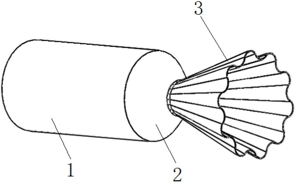
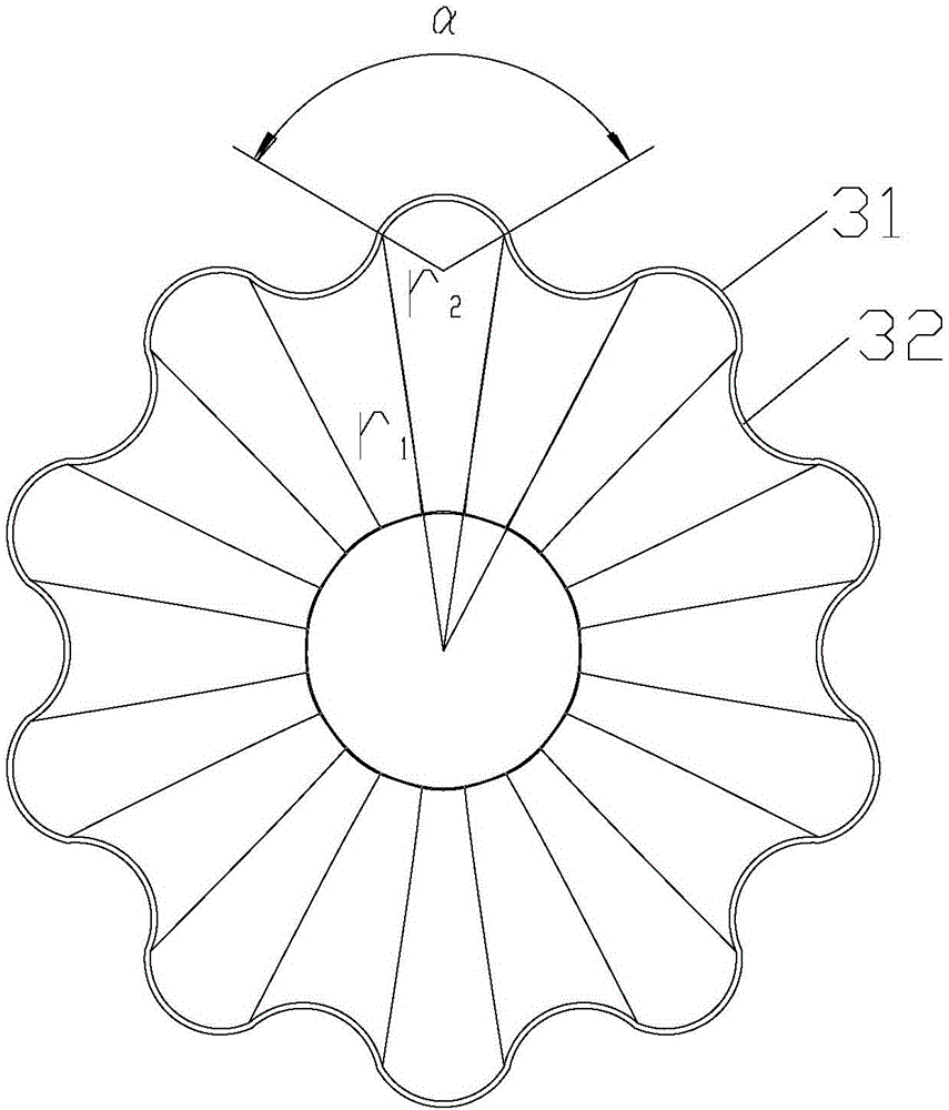
[0030] The present invention provides a nozzle, comprising an inlet pipe section 1, a transition pipe section 2 and an outlet pipe section 3 connected in sequence, the outlet pipe section 3 is formed as a tapered expansion pipe with an inner diameter gradually increasing along the direction from the inlet to the outlet, wherein the outlet The outer peripheral portion of the pipe section 3 includes protruding ribs 31 and concave ribs 32 formed alternately along the circumferential direction. On any cross section of the outlet pipe section 3, the contour of the inner wall surface of the outlet pipe section 3 is formed to be Concave and convex petals.

[0031] The...


PUM


Abstract

The invention discloses a nozzle and a steam ejector. The nozzle comprises an inlet pipe section (1), a transition pipe section (2) and an outlet pipe section (3) that are connected sequentially; a tapered expansion pipe with the inner diameter increasing along the direction from an inlet to an outlet forms at the outlet pipe section (3); a peripheral part of the outlet pipe section (3) comprises convex edge parts (31) and concave edge parts (32) that are formed in a staggered manner along the circumferential direction of the peripheral part sequentially, thus at any cross section of the outlet pipe section (3), a concave-convex petal shape is formed at an outline of an inner wall surface of the outlet pipe section (3) along the circumferential direction. With the adoption of the technical scheme, compared with a nozzle having a circular cross section, the nozzle with the cross section being petal-shaped has a greater perimeter on the condition that flow areas are equal, a contact area between the inner wall of the nozzle and a fluid is increased, the rolling suction and compounding effects of the fluid and other fluids at an outlet can be improved, an injection system can be improved, and a mixed fluid having better uniformity can be formed.

Description

technical field [0001] The invention relates to the field of fluid injection, in particular to a nozzle and a steam ejector. Background technique [0002] The steam ejector uses the supersonic low-pressure jet formed by the high-pressure steam in the Laval-type working nozzle to entrain the secondary fluid, and then forms a medium-pressure mixed steam at the outlet after being decelerated by diffusion. It is often used for vacuum preparation, fluid mixing, fluid transportation, etc. , has the characteristics of simple structure, convenient operation and maintenance. [0003] At present, the main methods to improve the performance of the steam ejector are: reasonable design of the structure and size of the ejector, mainly the area ratio of the inlet and outlet of the mixing section, the ratio of the throat area, etc. Due to the existence of shock waves in the steam injection process, a reasonable structure size can control the position and quantity of the shock waves, improv...

Claims


Application Information

Patent Timeline
IPC IPC(8): B05B1/34B05B7/04
CPCB05B1/34B05B7/04
Inventor 李岸然杨庆卫王颖聪
Owner CHINA SHENHUA ENERGY CO LTD
Why Eureka
Try Eureka