Floor heating pipeline groove forming method

A technology of floor heating pipes and forming methods, which is applied in the direction of forming tools, metal processing equipment, manufacturing tools, etc., which can solve the problems of difficulty in ensuring the dimensional consistency of floor heating pipe grooves and easy wrinkles, so as to ensure dimensional consistency and reduce internal stress , the effect of preventing wrinkles

Active Publication Date: 2017-02-15
ANHUI LINGFENG METALLURGICAL MACHINERY
View PDF6 Cites 2 Cited by
  • Summary
  • Abstract
  • Description
  • Claims
  • Application Information

AI Technical Summary

Problems solved by technology

[0009] The invention provides a floor heating pipe groove forming method to solve the problems in the prior art that the floor heating pipe groove cannot be accurately processed at one time, the floor heating pipe groove is prone to wrinkles after processing, and the size consistency of the floor heating pipe groove in the length direction is difficult to ensure. method, realizes the function of processing the floor heating pipe groove accurately and without wrinkles at one time, and ensures the dimensional consistency of the floor heating pipe groove in the length direction

Method used


Image

  • Floor heating pipeline groove forming method
  • Floor heating pipeline groove forming method
  • Floor heating pipeline groove forming method

Examples


Embodiment 1

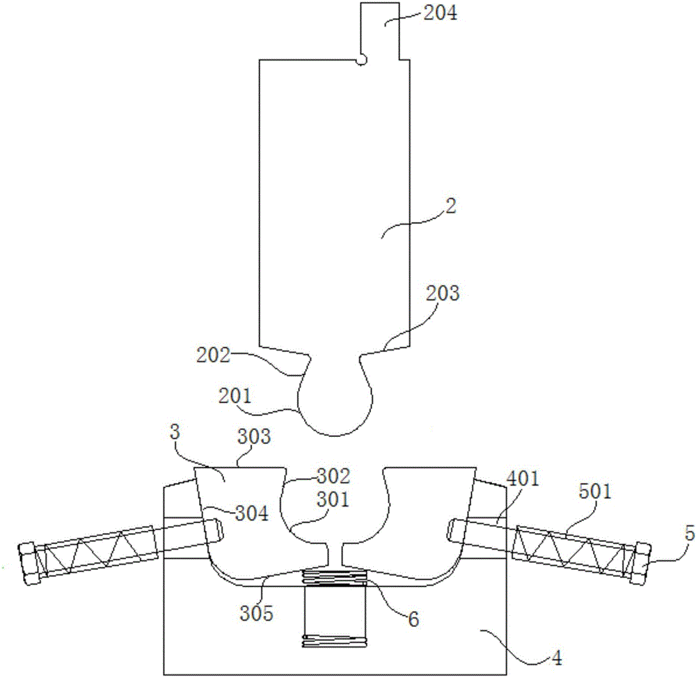
[0040] refer to figure 1 , figure 2 and image 3 , the combined mold for forming the floor heating pipe groove of the present embodiment includes an upper mold 2, a forming block 3, a lower mold base 4, a bolt 5 and a compression spring 501, and a U-shaped groove is opened on the lower mold base 4, and the left and right sides of the U-shaped groove Two molding blocks 3 are symmetrically arranged; side through holes 401 are symmetrically arranged on both sides of the lower mold base 4, and the bolts 5 pass through the side through holes 401 to be threadedly connected with the molding blocks 3, and the compression spring 501 is sleeved on the bolts 5, The diameter of compression spring 501 is greater than the inner diameter of side through hole 401, and one end of compression spring 501 is against the head of bolt 5, and the other end of compression spring 501 is against the outside of side through hole 401, and compression spring 501 ends and bolt 5. There is a rubber ring ...

Embodiment 2

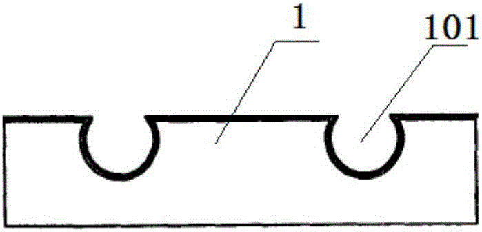
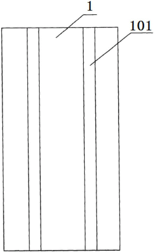
[0047] refer to figure 1 , figure 2 , image 3 and Figure 4 , a floor heating pipe groove forming method using the floor heating pipe groove forming combination mold of embodiment 1, comprising the following steps: 1), installing the mold: installing and fixing the upper mold 2 on the upper tool rest of the bending machine, and placing the lower The mold base 4 is installed and fixed on the lower tool rest of the bending machine, so that the upper mold 2 is directly facing the lower mold base 4 below, that is, the protrusion is located in the middle between the two arc-shaped depressions on the two forming blocks 3 Above; 2), feeding: place the heat conducting layer 1 blank on the top surface 303 of the two molding blocks 3, adjust the position of the heat conducting layer 1 blank, so that the part of the heat conducting layer 1 blank that needs to be stamped out of the floor heating pipe groove 101 is located at the two 3), stamping: the upper die 2 presses down with the...

Embodiment 3

[0049] refer to figure 1 , figure 2 and image 3 , The manufacturing method of the floor heating pipe groove forming combination mold of the present embodiment includes the following steps: step (1), blanking; step (2), forging; step (3), rough machining; step (4), punching; Step (5), heat treatment, the heat treatment process in step (5) is quenching and tempering treatment, the hardness of mold after quenching and tempering treatment is HRC40~45, and the hardness of mold after quenching and tempering treatment in the specific present embodiment is HRC40; Step (6 ),finishing.

[0050] Wherein, the structure of the combined mold for forming the floor heating pipe groove is as follows: the combined mold for forming the floor heating pipe groove includes an upper mold 2, a forming block 3, a lower mold base 4, a bolt 5 and a compression spring 501, and the lower mold base 4 is provided with a U-shaped groove, Two molding blocks 3 are symmetrically arranged in the U-shaped gr...


PUM

PropertyMeasurementUnit
thicknessaaaaaaaaaa
thicknessaaaaaaaaaa
diameteraaaaaaaaaa

Abstract

The invention discloses a floor heating pipeline groove forming method, and relates to the field of forming combination molds special for floor heating pipeline grooves. The floor heating pipeline groove forming method includes the following steps that (1) a mold is installed; (2) feeding is performed; (3) stamping is conducted, two forming blocks are subjected to acting force of a heat conduction layer blank and can rotate towards the middle part to be folded synchronously under the combined effect of compressed springs at the two sides of a lower mold base and a supporting spring at the bottom of a U-shaped groove, and a protruding part can be wrapped by bending the heat conduction layer blank; and (4) resilience is carried out, the protruding part can enter the gap located between the two forming blocks completely when an upper mold reaches the maximum stroke, and the heat conduction layer blank can wrap the protruding part completely; and then, the two forming blocks rotate towards the two sides to be separated synchronously, and the heat conduction layer blank can be ejected out. By means of the floor heating pipeline groove forming method, the function of precisely processing the floor heating pipeline grooves at a time in a wrinkle-free mode is achieved, and dimensional consistency of the floor heating pipeline grooves in the length direction is guaranteed.

Description

[0001] The patent application of the present invention is a divisional application with the application number: 2015107913848. The filing date of the original application is: 2015-11-16. The name of the invention is: a combined mold for forming floor heating pipe grooves and its forming method. technical field [0002] The invention relates to the field of special forming composite molds for floor heating pipe grooves, and more specifically relates to a forming method for floor heating pipe grooves. Background technique [0003] Floor heating has become the mainstream of domestic heating methods, but the traditional installation method of floor heating is called wet floor heating. High, the thermal effect time is very long, accounting for about 10 centimeters of the building's floor height, and it has a large load on the building. Aiming at the many shortcomings of the wet floor heating technology, dry floor heating technology products have emerged in recent years, namely dr...

Claims


Application Information

Patent Timeline
Patent Type & Authority Applications(China)
IPC IPC(8): B21D37/10B21D5/06
CPCB21D5/06B21D37/10
Inventor 刘道豹刘威刘发仙刘国庆
Owner ANHUI LINGFENG METALLURGICAL MACHINERY
Why Eureka
Try Eureka