Special drilling equipment for porous long shaft

A special equipment, long-axis technology, used in drilling/drilling equipment, boring/drilling, metal processing equipment, etc., can solve the problems of insufficient travel of the table guide rail, poor economy and adaptability, and inability to clamp , to achieve the effect of simple structure, low cost, easy installation and manufacturing

Active Publication Date: 2017-02-15
重庆鑫宝田冶金工业有限责任公司
View PDF8 Cites 2 Cited by
  • Summary
  • Abstract
  • Description
  • Claims
  • Application Information

AI Technical Summary

Problems solved by technology

[0002] In mechanical processing, it is often encountered in the processing of long shafts or pipe parts, the most common of which is to drill holes on the shaft. Because the shaft is relatively long, usually two meters or three meters, or even longer, this If you use general-purpose equipment to drill holes, it may greatly exceed the working movement size of the machine tool, resulting in failure to clamp, or the actuator, such as insufficient travel of the workbench guide rail; if you use CNC equipment, use the tool connected to the spindle ( Drill bit) moves to drill a series of holes with different positions, and it also faces the limitation of the spindle movement stroke. At this time, if these general-purpose equipment are improved, the cost is huge, and the economy and adaptability are poor.

Method used


Image

  • Special drilling equipment for porous long shaft
  • Special drilling equipment for porous long shaft
  • Special drilling equipment for porous long shaft

Examples


Embodiment Construction

[0037] The implementation of the present invention will be illustrated by specific specific examples below, and those skilled in the art can easily understand other advantages and effects of the present invention from the contents disclosed in this specification.

[0038] Below in conjunction with accompanying drawing and embodiment the present invention will be further described:

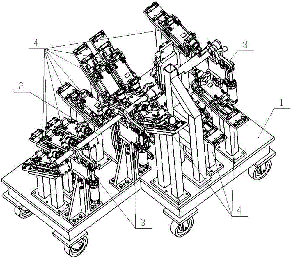
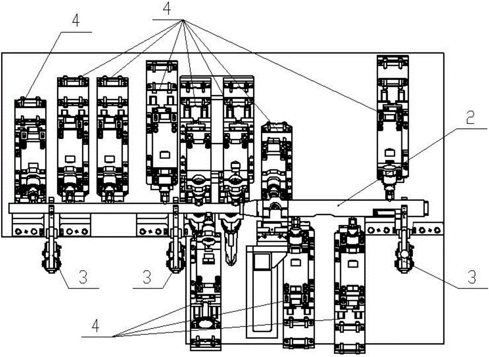
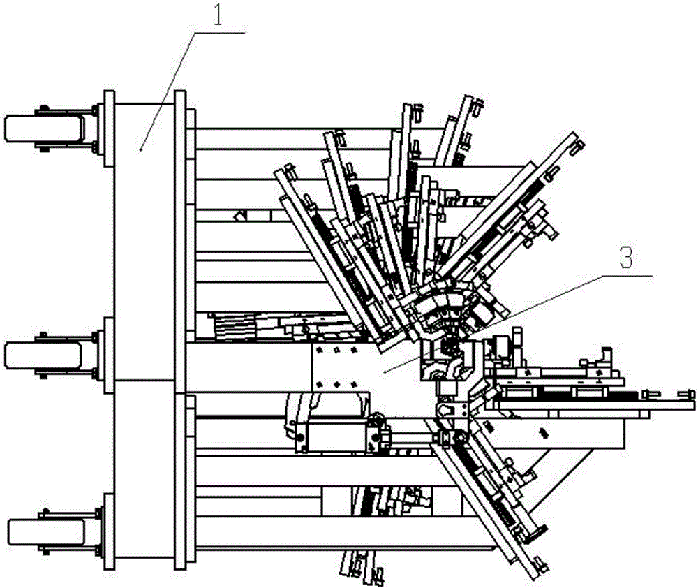
[0039] Such as figure 1 -Shown in -5, a kind of drilling special equipment of multi-hole long axis, comprises support 1 and is located on support 1 and is used for the fixture 3 that clamps long axis 2 usefulness and is used for drilling on long axis 2 Gun drill module 4.

[0040] Such as Figure 6As shown in -9, the clamp 3 includes a support frame 5, and the support frame 5 includes a pair of right-angled L-shaped steel plates 501 symmetrically arranged on the left and right, and a right-angled triangle is arranged between the two right-angled plates of the L-shaped steel plate 501. Ribs 502 i...


PUM


Abstract

The invention discloses special drilling equipment for a porous long shaft. The special drilling equipment comprises a machine base, clamps and gun drilling modules, wherein each clamp comprises a supporting frame; each supporting frame comprises a pair of L-shaped steel plates which clamp a supporting plate with a notch; a Z-shaped pressure plate is arranged above the opening of each notch; a lower horizontal plate of each Z-shaped plate is hinged with the corresponding supporting plate; the tail end of each lower horizontal plate is hinged with a first hydraulic rod; and each gun drilling module comprises a gun drill, a gun drill mounting base and second hydraulic rods, wherein the second hydraulic rods are hinged with a clamp mounting base, and a fastening nut and a supporting screw of a supporting barrel which is fixedly equipped with a supporting shaft are sequentially arranged between the two second hydraulic rods. The gun drill mounting base comprises a clamp base, a tail base and a jacket which comprises an upper blocking base and a lower blocking base; the clamp base moves under the action of a third hydraulic rod; the clamps are arranged in one side of the machine base; notches of all clamps are on the same horizontal straight line; and the gun drilling modules are separately arranged at the two sides of the long shaft. The special drilling equipment is simple in structure, is convenient to mount and manufacture, is flexible and various in drilling performance, and is strong in adaptation.

Description

technical field [0001] The invention belongs to the technical field of mechanical processing, and in particular relates to a drilling device for shaft parts. Background technique [0002] In mechanical processing, it is often encountered in the processing of long shafts or pipe parts, the most common of which is to drill holes on the shaft. Because the shaft is relatively long, usually two meters or three meters, or even longer, this If you use general-purpose equipment to drill holes, it may greatly exceed the working movement size of the machine tool, resulting in failure to clamp, or the actuator, such as insufficient travel of the workbench guide rail; if you use CNC equipment, use the tool connected to the spindle ( Drill bit) moves to drill a series of holes with different positions, and then also faces the limitation of the main shaft movement stroke. At this time, if these general-purpose equipment are improved, the cost is huge, and the economy and adaptability are ...

Claims


Application Information

Patent Timeline
Patent Type & Authority Applications(China)
IPC IPC(8): B23B41/00B23Q3/08B23B47/00
CPCB23B41/003B23B47/00B23Q3/082
Inventor 刘鑫桃李果龚霁
Owner 重庆鑫宝田冶金工业有限责任公司
Why Eureka
Try Eureka