Fiber bragg grating intelligent steel strand and manufacturing method thereof

A smart steel strand and fiber grating technology, applied in the field of monitoring, can solve problems such as poor shear resistance and bending resistance, and insufficient monitoring range of fiber grating sensors, so as to improve accuracy and persuasiveness, improve deployment survival rate and The effect of service life

Inactive Publication Date: 2017-02-15
朱万旭 +1
View PDF6 Cites 16 Cited by
  • Summary
  • Abstract
  • Description
  • Claims
  • Application Information

AI Technical Summary

Problems solved by technology

[0004] However, due to the inherent glass brittleness of the optical fiber material, its shear and bending resistance is poor, and special protection is required during application; at the same time, the ultimate tensile st

Method used


Image

  • Fiber bragg grating intelligent steel strand and manufacturing method thereof
  • Fiber bragg grating intelligent steel strand and manufacturing method thereof
  • Fiber bragg grating intelligent steel strand and manufacturing method thereof

Examples


Embodiment Construction

[0028] The embodiments of the present invention will be described in detail below with the accompanying drawings and examples, so as to fully understand and implement the implementation process of how the present invention applies technical means to solve technical problems and achieve technical effects.

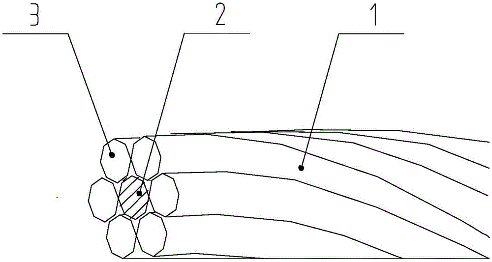
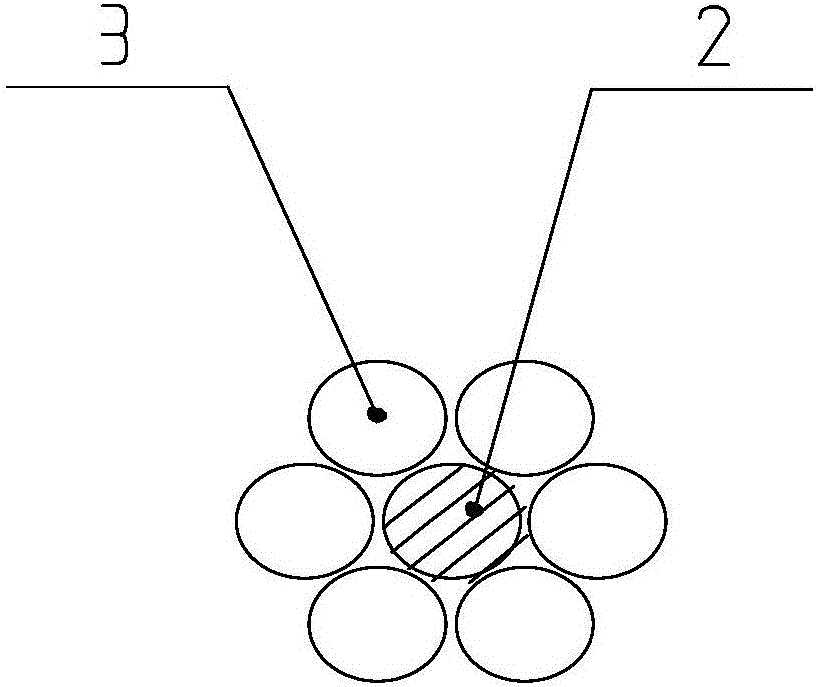
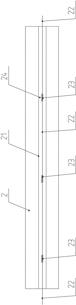
[0029] like Figure 1 to Figure 4 As shown, the fiber grating smart steel strand 1 of the embodiment of the present invention includes a center wire 2, and an edge wire 3 twisted with the center wire 2; the center wire 2 is provided with at least one groove 21, and the groove 21 is placed with The optical fiber 22, at least one grating 23 is engraved on the optical fiber 22.

[0030] The grooves 21 are longitudinal grooves, and the number of the grooves 21 is 1 to 6. The groove 21 is 0.1-0.8 mm deep and 0.1-1.5 mm wide, and the optical fiber 22 is pasted in the groove 21 by an adhesive 24 .

[0031] The embodiment of the present invention also provides a method for manufac...


PUM


Abstract

The invention provides a fiber bragg grating intelligent steel strand. The fiber bragg grating intelligent steel strand comprises a center wire and side wires, wherein the center wire and the side wires are twisted; at least one groove is formed in the center wire, optical fiber is placed in the grooves, and at least one grating is carved in the optical fiber. The invention further provides a manufacturing method of the fiber bragg grating intelligent steel strand. The technical problem that the laying process survival rate is low and monitoring range is narrow when stress conditions of the steel strand is monitored by an existing fiber bragg grating are solved.

Description

technical field [0001] The invention belongs to the technical field of monitoring, and in particular relates to a fiber grating intelligent steel strand and a manufacturing method thereof. Background technique [0002] Steel strands such as tie rods in tied arch bridges, suspension bridges, cables in cable-stayed bridges, internal and external prestressed tendons, and anchor rods in rock and soil are the key stress components in the structure. The working state during their use is directly related to the structure. Safety. Due to the coupling effect of factors such as environmental erosion, material aging and long-term load effects during use, damage accumulation is inevitable, resulting in the reduction of various functions, threatening the safety of the structure during its service life, and even in extreme cases. lead to catastrophic consequences. Therefore, it is necessary to monitor the above components. [0003] The traditional monitoring methods are mainly accelera...

Claims


Application Information

Patent Timeline
IPC IPC(8): D07B1/14D07B1/06G01L1/24
CPCD07B1/0693D07B1/145D07B2201/2095D07B2205/3025G01L1/246D07B2801/10D07B2301/259D07B2301/5577
Inventor 朱万旭覃荷瑛
Owner 朱万旭
Why Eureka
Try Eureka