Hydraulic pulper

A technology of hydraulic pulper and pulp outlet, which is applied in the direction of textile and papermaking, raw material separation, fiber raw material processing, etc. It can solve the problems of dead angle, small volume utilization rate, and energy waste, so as to prevent energy waste and improve energy utilization. The effect of high efficiency and high volume utilization

Active Publication Date: 2017-02-15
江苏富星纸业有限公司
View PDF10 Cites 8 Cited by
  • Summary
  • Abstract
  • Description
  • Claims
  • Application Information

AI Technical Summary

Problems solved by technology

[0005] The object of the present invention is to provide a hydraulic pulper to solve the problems of σ, G, D-shaped tank volume utilization rate is small, there are dead ends, and energy waste

Method used


Image

  • Hydraulic pulper
  • Hydraulic pulper
  • Hydraulic pulper

Examples


Embodiment Construction

[0017] The present invention will be described in further detail below by means of specific embodiments:

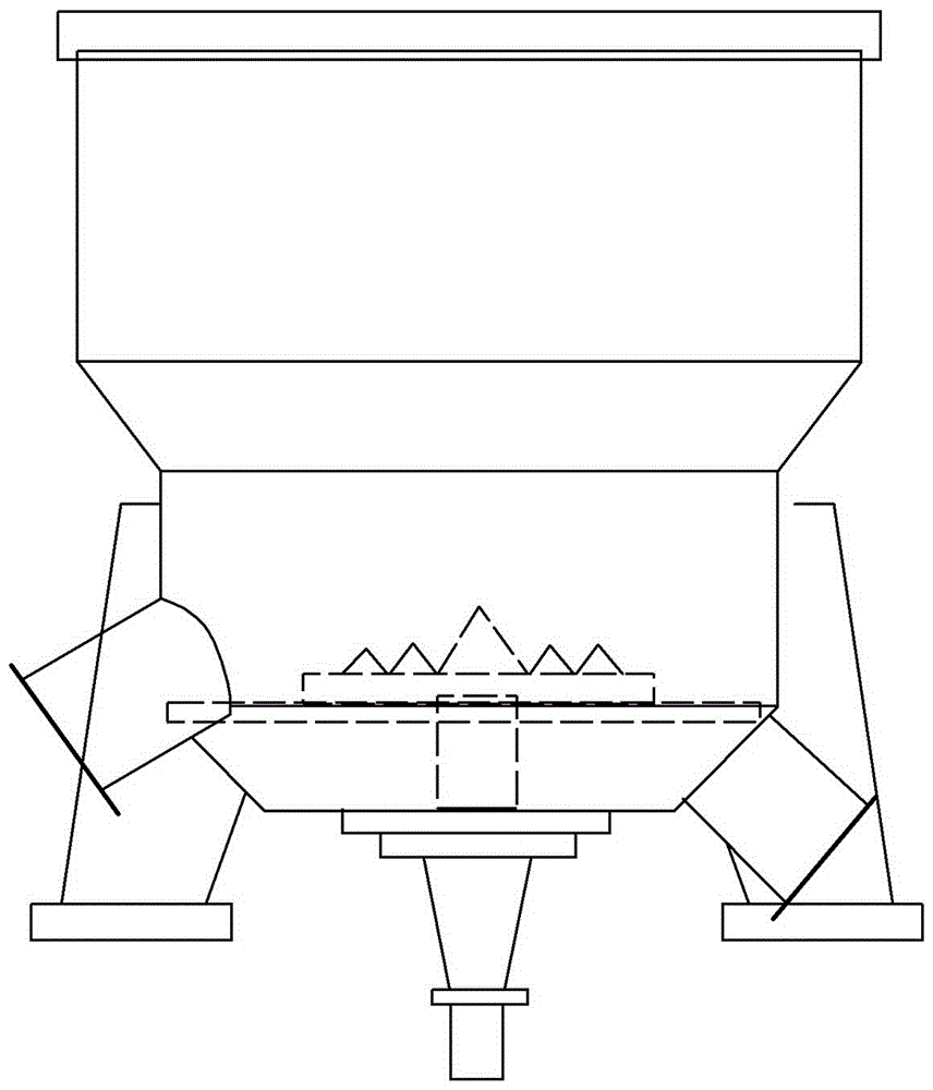
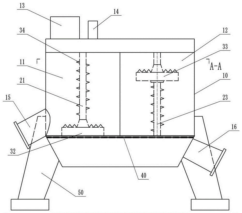
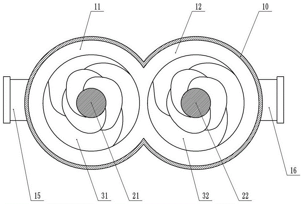
[0018] The reference signs in the drawings of the description include: tank body 10, first cavity 11, second cavity 12, blanking opening 13, water spray pipe 14, slag outlet 15, slurry outlet 16, first pillar 21 , The second pillar 22, the first rotor 31, the second rotor 32, the cutter teeth 33, the sieve plate 40, and the bracket 50.

[0019] like figure 2 , image 3 As shown, the hydraulic pulper includes a tank body 10, a rotor, a sieve plate 40, a bracket 50, a first pillar 21 and a second pillar 22, the sieve plate 40 is located at the lower end of the tank body 10, and the bracket 50 is used to support the tank body 10. The cross section of the tank body 10 is "8" shape, and includes a first cavity 11 on the left side and two cavities on the right side; a first rotor 31 and a second rotor 32 . The first pillar 21 is rotatably installed in the middle of the fir...


PUM


Abstract

The invention discloses a hydraulic pulper. The hydraulic pulper comprises a tank body, rotors, a screen plate, a bracket, a first support column and a second support column, wherein the screen plate is positioned at the lower end of the tank body, and is used for supporting the tank body; a material dropping opening and a water spray pipe are arranged at the top part of the tank body, the bottom part of the tank body is provided with a slag outlet and a pulp outlet, the slag outlet is positioned above the screen plate, and the pulp outlet is positioned under the screen plate; the cross section of the tank body is in a splay shape, and the tank body comprises a first cavity and a second cavity; the first support column is arranged in the middle of the first cavity, and the second support column is arranged in the middle of the second cavity; the rotors comprise a first rotor and a second rotor, motors are respectively arranged at the lower parts of the first rotor and the second rotor, and the rotation directions of the two motors are opposite; the first rotor is sheathed on the first support column, the second rotor is sheathed on the second support column, and the first rotor and the second rotor are not positioned on the same horizontal surface. Compared with the prior art, the hydraulic pulper has the advantages that the dead corner is avoided, the utilization rate of energy is higher, and the pulping efficiency is higher.

Description

technical field [0001] The invention belongs to the technical field of papermaking equipment, in particular to a hydraulic pulper. Background technique [0002] The hydraulic pulper is to disintegrate the pulp board, waste paper (cardboard), etc. soaked in water through hydraulic and mechanical force, and disintegrate the pulp board, waste paper (cardboard), etc. into pulp fiber suspension, and the heavy, Large impurities are separated from the fibers. The structure of the existing hydropulper is shown in Figure 1, which consists of a tank body, a rotor (or cutter head) located at the bottom of the tank body, a sieve plate located below the rotor, transmission parts, and a support frame. The top of the tank body is provided with a blanking port and a water spray pipe, the coarse slag outlet is located at the bottom of the tank body and above the sieve plate, and the fine pulp outlet is located below the sieve plate. [0003] When the hydraulic pulper is working, the rotor ...

Claims


Application Information

Patent Timeline
Patent Type & Authority Applications(China)
IPC IPC(8): D21B1/34
CPCD21B1/345D21B1/347
Inventor 李泽世张善芳彭绅彭铂祯
Owner 江苏富星纸业有限公司
Why Eureka
Try Eureka