Omnibearing longhole drilling machine

A deep hole drilling rig, all-round technology, applied in the direction of earthwork drilling, drilling equipment, drilling equipment and methods, etc., can solve the problems of increased walking resistance, poor stability, and inability to support the mast at all angles, reaching the diameter of the oil cylinder The effect of reducing and propulsive resistance reduction

Inactive Publication Date: 2017-02-15
SHAANXI STAR EXPLOSION SAFETY POLYTRON TECH INC
View PDF11 Cites 3 Cited by
  • Summary
  • Abstract
  • Description
  • Claims
  • Application Information

AI Technical Summary

Problems solved by technology

The disadvantage is that the sliding resistance is large. Due to the large amount of dust underground, a large amount of dust enters the U-shaped groove, which is difficult to clean, which increases the walking resistance and accelerates the damage of the slide rail;
[0005] 3. The angle adjustment mechanism of the mast has a complex structure and poor stability
Typically, it is a fixed force support for the crank connecting rod mechanism, and the drilling rig vibrates seriously during drilling operations;
[0006] 4. The support of the drilling rig depends on the upright oil cylinder support, which cannot support the mast at all angles;
[0007] 5. There are many welded structures, and the overall structural strength is poor; the underground corrosion intensity is high, and weld cracks are prone to crevice corrosion, which accelerates the damage of important structural parts;
[0008] 6. The narrow downhole space requires the drilling rig to be small in size, and it is difficult for the drilling rig to realize the telescoping function for the requirement of small volume and high thrust

Method used


Image

  • Omnibearing longhole drilling machine
  • Omnibearing longhole drilling machine
  • Omnibearing longhole drilling machine

Examples


Embodiment Construction

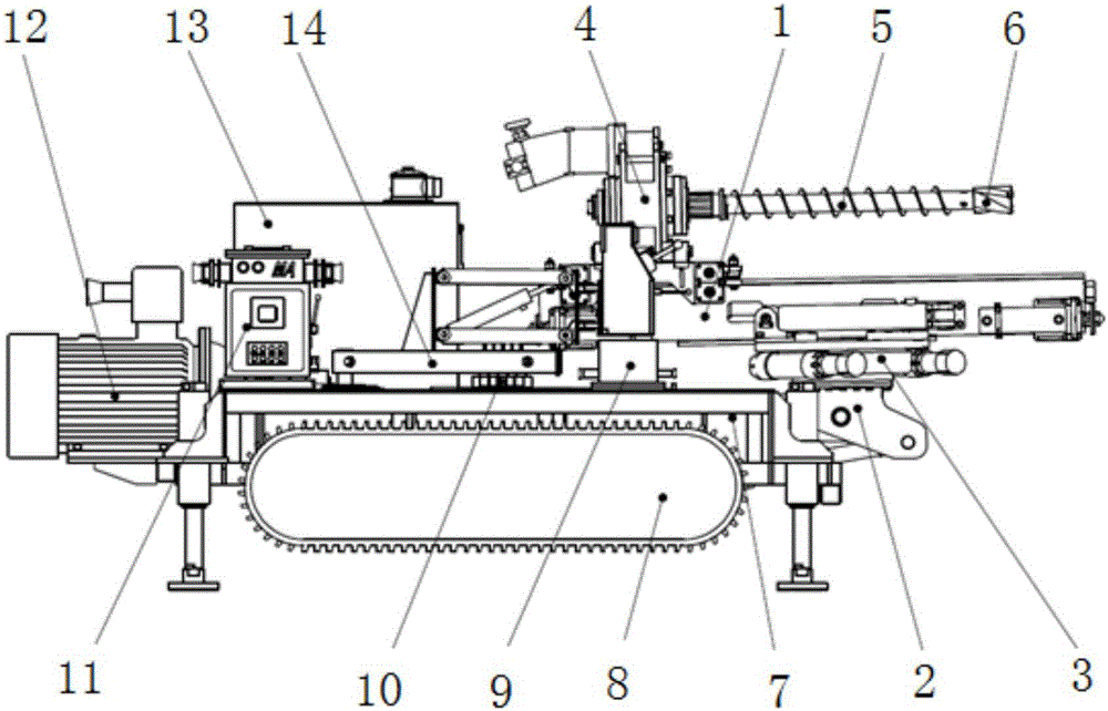
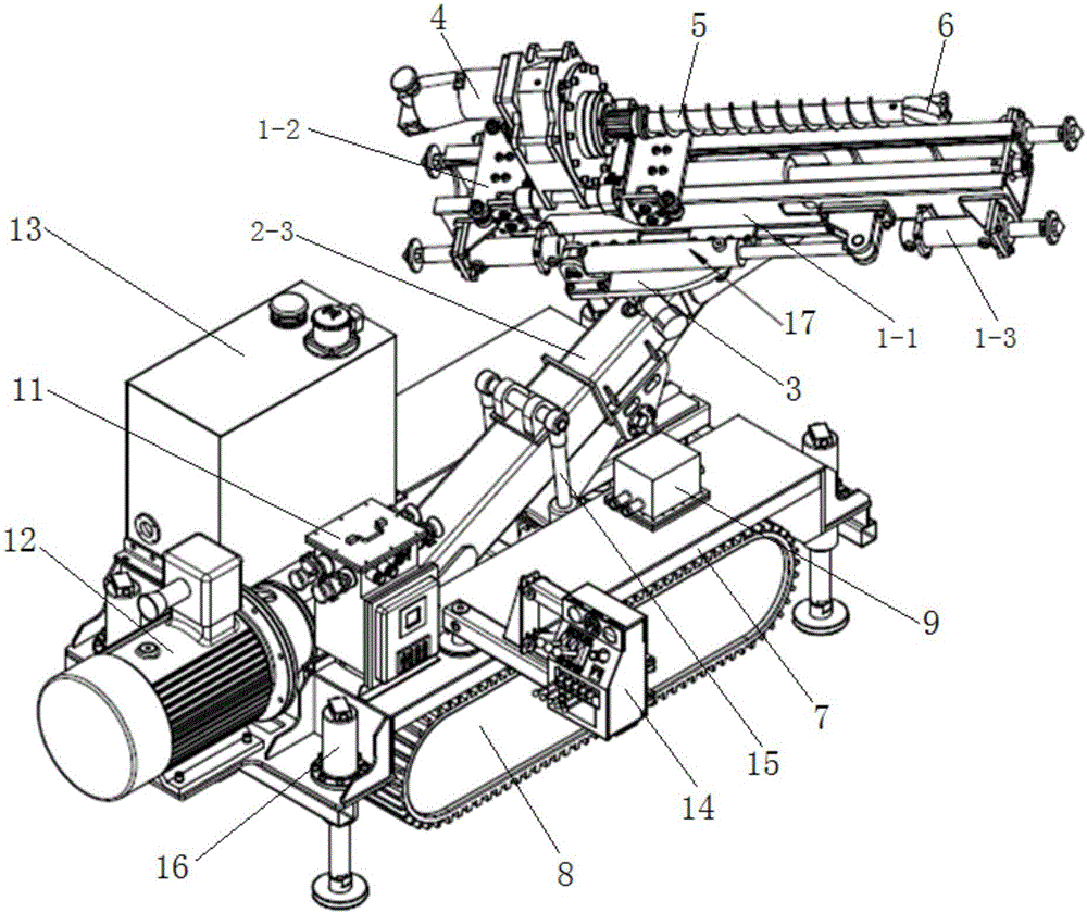
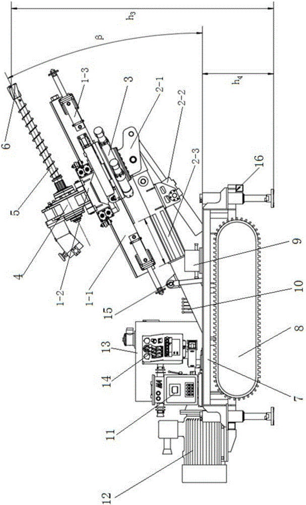
[0051] The first omni-directional deep hole drilling rig of the present invention comprises a frame, crawlers and leg cylinders are installed under the frame, hydraulic pumps, oil tanks and operating components are installed on the frame, and luffing units, Rolling friction unit and drilling rig unit; the non-oscillating end of the luffing unit is fixed on the frame, the rolling friction unit is set on the swinging end of the luffing unit, and the drilling rig unit is set on the rolling friction unit, and the rolling friction unit can be adjusted through the luffing unit And the drilling unit swings within the range of 0-105°, and the rolling friction unit can drive the drilling unit to roll along its axial direction.

[0052] The second omni-directional deep hole drilling machine of the present invention can also be based on the first one, and a rotary unit is also provided between the luffing end of the luffing unit and the rolling friction unit, and the rotary unit can drive...


PUM


Abstract

The invention discloses an omnibearing longhole drilling machine. The omnibearing longhole drilling machine comprises a machine frame. Tracks and supporting leg oil cylinders are mounted under the machine frame. A hydraulic pump, an oil tank and a control part are mounted on the machine frame. An amplitude change unit, a rolling friction unit and a drilling machine unit are arranged on the machine frame. The non-swing end of the amplitude change unit is fixedly arranged on the machine frame. The rolling friction unit is arranged at the swing end of the amplitude change unit. The drilling machine unit is arranged on the rolling friction unit. The rolling friction unit and the drilling machine unit can be adjusted to swing within the range of 0-105 degrees through the amplitude change unit. The rolling friction unit can drive the drilling machine unit to walk in a rolling mode in the axial direction of the rolling friction unit. The omnibearing longhole drilling machine can complete oblique hole drilling operation with the inclination angle being 0-26 degrees within the range of 800-3000 mm; and the drilling machine can complete drilling operation of upward and downward vertical holes and drilling operation with any angles formed with the vertical holes through adjustment of an amplitude change oil cylinder, the supporting leg oil cylinders and a rotation assembly.

Description

technical field [0001] The invention belongs to the field of drilling equipment, in particular to an omnidirectional deep hole drilling machine. Background technique [0002] In the field of coal mining, with the development of technology, new drilling rigs with various functions have been applied. Their basic structures are similar and their basic functions are the same. The drilling functions of horizontal holes, inclined holes and vertical holes have been basically realized. In the past, when the traditional technology was adopted in the design of the drilling rig, the design bottleneck of the drilling rig function was caused due to the narrow downhole space, which is mainly summarized as follows: [0003] 1. The propulsion mechanism of the drilling rig mast adopts rack and pinion double-speed transmission mechanism. The advantage of this structure is that it solves the problem of insufficient space and can double the stroke of the drilling rig. The disadvantage is that t...

Claims


Application Information

Patent Timeline
IPC IPC(8): E21B7/02E21B15/04
CPCE21B7/02E21B7/024E21B15/04E21B15/045
Inventor 文新国胡重杰靳党林张文
Owner SHAANXI STAR EXPLOSION SAFETY POLYTRON TECH INC
Why Eureka
Try Eureka