A luffing rolling friction drilling mechanism

A technology of rolling friction and drilling rigs, which is applied in the direction of earthwork drilling, drilling equipment, drilling equipment and methods, etc., can solve the problems of poor overall structural strength, increased walking resistance, and poor stability, so as to improve stiffness and stability, The effect of enhanced structural strength and reduced propulsion resistance

Active Publication Date: 2019-03-12
SHAANXI STAR EXPLOSION SAFETY POLYTRON TECH INC
View PDF6 Cites 0 Cited by
  • Summary
  • Abstract
  • Description
  • Claims
  • Application Information

AI Technical Summary

Problems solved by technology

The disadvantage is that the sliding resistance is large. Due to the large amount of dust underground, a large amount of dust enters the U-shaped groove, which is difficult to clean, which increases the walking resistance and accelerates the damage of the slide rail;
[0005] 3. The angle adjustment mechanism of the mast has a complex structure and poor stability
Typically, it is a fixed force support for the crank connecting rod mechanism, and the drilling rig vibrates seriously during drilling operations;
[0006] 4. The support of the drilling rig depends on the upright oil cylinder support, which cannot support the mast at all angles;
[0007] 5. There are many welded structures, and the overall structural strength is poor; the underground corrosion intensity is high, and weld cracks are prone to crevice corrosion, which accelerates the damage of important structural parts;
[0008] 6. The narrow downhole space requires the drilling rig to be small in size, and it is difficult for the drilling rig to realize the telescoping function for the requirement of small volume and high thrust

Method used


Image

  • A luffing rolling friction drilling mechanism
  • A luffing rolling friction drilling mechanism
  • A luffing rolling friction drilling mechanism

Examples


Embodiment Construction

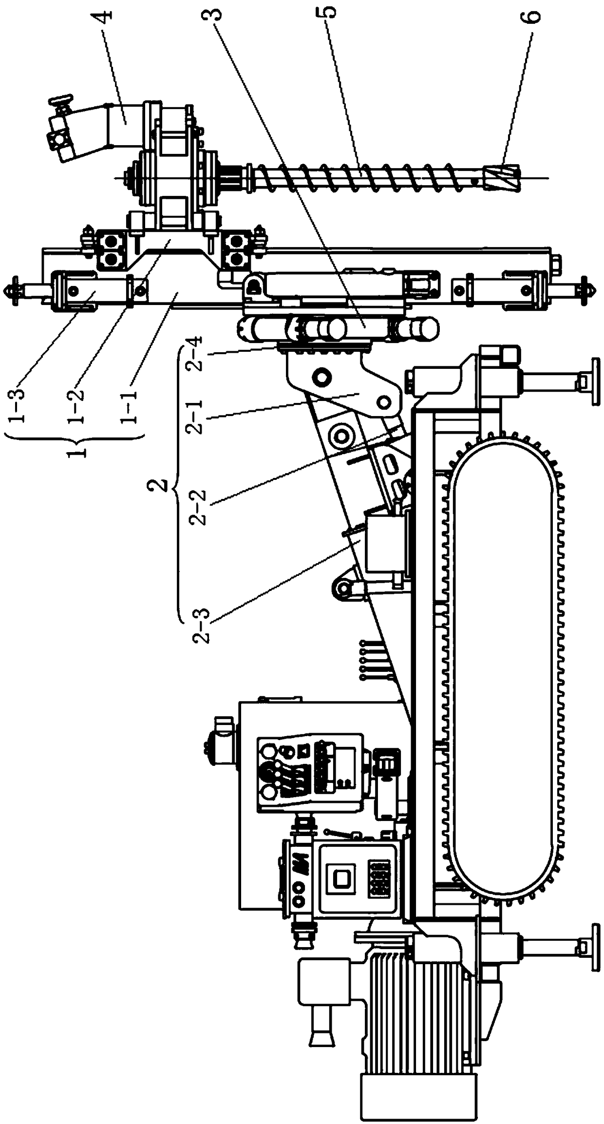
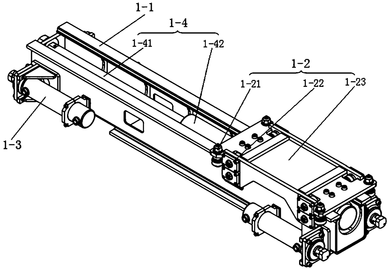
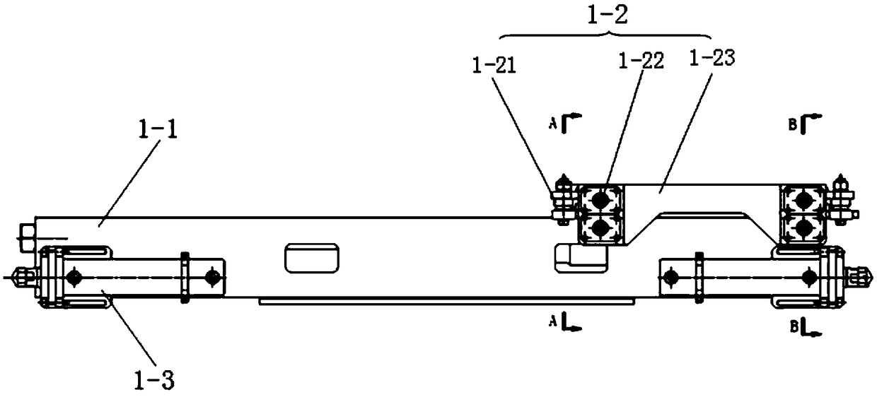
[0043] The luffing rolling friction drilling machine component of the present invention includes a drilling unit, an luffing unit and a rolling friction unit; the luffing unit includes a beam, and the beam is a telescopic beam, and the beam includes telescopic beams and Fix the beam, and set a track along the length direction on the telescopic beam; the fixed beam end of the luffing unit (2) is fixed on the drilling rig, and the rolling friction unit is set on the telescopic beam end of the luffing unit, and the rolling friction can be adjusted through the luffing unit The unit and the drill head swing within the range of 0-105°, and the rolling friction unit can drive the drill head to roll along its axial direction; the drill unit includes the drill head, drill pipe and drill bit, and the drill head is installed on the rolling friction On the unit, the drill rod and the drill bit are installed on the drilling rig head in turn.

[0044] In the rolling friction unit of the pre...


PUM


Abstract

The invention discloses an amplitude variation rolling friction drilling machine component. The amplitude variation rolling friction drilling machine component comprises a drilling machine unit, an amplitude variation unit and a rolling friction unit. The amplitude variation unit comprises a cross beam which is a telescopic cross beam. The cross beam comprises a telescopic beam and a fixed beam which are sleeved with each other, and tracks are arranged on the telescopic beam in the length direction in a spaced mode. The fixed beam end of the amplitude variation unit is fixedly arranged on a drilling machine. The telescopic beam end of the amplitude variation unit is provided with the rolling friction unit. The rolling friction unit and the head of the drilling machine can be adjusted to swing in the range of 0-105 degrees through the amplitude variation unit, and the rolling friction unit can drive the head of the drilling machine to walk in a rolling mode in the axial direction of the rolling friction unit. The drilling machine unit comprises a drilling machine power head, a drilling rod and a drilling bit. The drilling machine power head is installed on the rolling friction unit. The drilling rod and the drilling bit are sequentially installed on the drilling machine power head.

Description

technical field [0001] The invention belongs to the field of drilling equipment, in particular to a variable-amplitude rolling friction drilling machine component. Background technique [0002] In the field of coal mining, with the development of technology, new drilling rigs with various functions have been applied. Their basic structures are similar and their basic functions are the same. The drilling functions of horizontal holes, inclined holes and vertical holes have been basically realized. In the past, when the traditional technology was adopted in the design of the drilling rig, the design bottleneck of the drilling rig function was caused due to the narrow downhole space, which is mainly summarized as follows: [0003] 1. The propulsion mechanism of the drilling rig mast adopts rack and pinion double-speed transmission mechanism. The advantage of this structure is that it solves the problem of insufficient space and can double the stroke of the drilling rig. The dis...

Claims


Application Information

Patent Timeline
Patent Type & Authority Patents(China)
IPC IPC(8): E21B7/02E21B15/00
CPCE21B7/023E21B15/003
Inventor 文新国胡重杰靳党林张文
Owner SHAANXI STAR EXPLOSION SAFETY POLYTRON TECH INC
Why Eureka
Try Eureka