Eureka AIR delivers breakthrough ideas for toughest innovation challenges, trusted by R&D personnel around the world.

Underground information acoustic wave signal generating system

A technology of sound wave signal and generation system, which is applied in the direction of wellbore/well components, measurement, earthwork drilling and production, etc. It can solve the problems of downhole noise interference, inability to realize two-way information transmission, transmission cable wear or twisting, etc., to achieve anti-corrosion Strong noise interference ability, reduced additional operation risk, and wide application range

Active Publication Date: 2017-02-15
CHINA UNIV OF PETROLEUM (EAST CHINA)
View PDF4 Cites 4 Cited by
  • Summary
  • Abstract
  • Description
  • Claims
  • Application Information

AI Technical Summary

Problems solved by technology

[0004] (1) Wired transmission: Although it can realize fast and large-scale transmission of downhole information, the rotation of the drill string during the drilling process will easily cause the transmission cable to be worn or twisted, affecting normal drilling
[0005] (2) Drilling fluid pulse transmission: The pressure wave of drilling fluid is used as the transmission carrier, which has a strong dependence on drilling fluid, and has disadvantages such as slow transmission rate, susceptibility to downhole noise interference, and inability to realize two-way information transmission.
[0006] (3) Electromagnetic wave transmission: Although it gets rid of the dependence on drilling fluid and can realize two-way transmission of downhole information, it has the disadvantages of dependence on the formation, large attenuation in the formation, poor versatility, and high cost.

Method used


Image

  • Underground information acoustic wave signal generating system
  • Underground information acoustic wave signal generating system
  • Underground information acoustic wave signal generating system

Examples


Embodiment Construction

[0036] In the following, the present invention will be specifically described through exemplary embodiments. It should be understood, however, that elements, structures and characteristics of one embodiment may be beneficially incorporated in other embodiments without further recitation.

[0037] In the description of the present invention, it should be noted that the orientation or positional relationship indicated by the terms "inner", "outer", "upper", "lower", etc. is based on the positional relationship shown in the drawings, and is only for convenience The present invention is described and simplified descriptions do not indicate or imply that the device or element referred to must have a specific orientation, be constructed and operate in a specific orientation, and thus should not be construed as limiting the present invention. In addition, the terms "first", "second", and "third" are used for descriptive purposes only, and should not be construed as indicating or impl...


PUM


Abstract

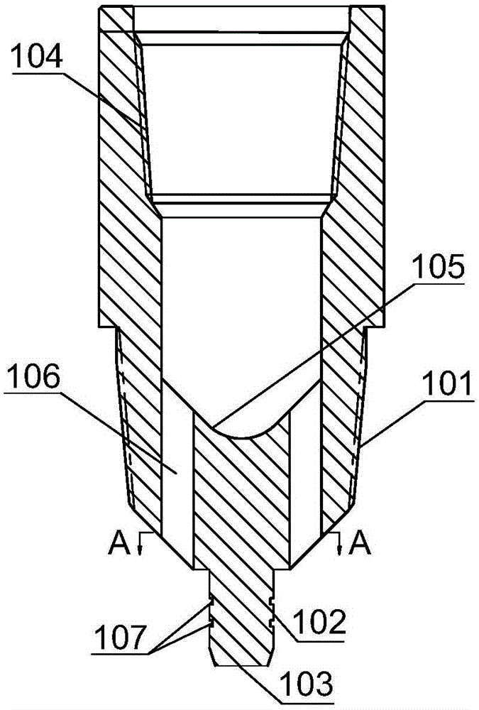
The invention relates to an underground information acoustic wave signal generating system which comprises an upper connector and an instrument bin protecting cylinder connected with one end of the upper connector. A transducer protecting cylinder, an instrument bin and a detecting instrument standby connecting pipe which are sequentially connected are installed in the instrument bin protecting cylinder. One end of the transducer protecting cylinder is matched with the upper connector. The end, connected with the detecting instrument standby connecting pipe, of the instrument bin is connected with one end of the instrument bin protecting cylinder. A transducer is installed in the transducer protecting cylinder. A transducer driving circuit, a transcoding circuit and an encoding circuit which are sequentially connected are arranged in the instrument bin. Normal drilling is ensured, the aim of converting collected shaft bottom drilling information into sound wave signals to be send is achieved, noise interference resistance is strong, the real-time and accuracy conversion of drilling information can be achieved, and the application range is wide.

Description

technical field [0001] The invention belongs to the technical field of petroleum and natural gas drilling engineering, and relates to an information transmission system while drilling, in particular to an acoustic signal generation system for downhole information based on acoustic waves. Background technique [0002] According to the current geological conditions and natural environmental conditions encountered in the exploitation of oil and gas resources in the world, the future oil drilling industry will encounter severe challenges of more complex geological conditions and harsher natural environments. Therefore, the downhole process monitoring of oil and gas drilling has put forward higher requirements. requirements. [0003] The high-speed transmission and effective acquisition of downhole information is the key to accurate monitoring of downhole processes and the key technology to achieve fast and high-quality drilling. The downhole information transmission methods tha...

Claims


Application Information

Patent Timeline
Patent Type & Authority Applications(China)
IPC IPC(8): E21B47/16
CPCE21B47/16
Inventor 管志川王庆刘永旺李志刚赵国山刘逸儒杨建兴孙玉林梁赉宋国旗
Owner CHINA UNIV OF PETROLEUM (EAST CHINA)
Why Eureka
Eureka Blog
Learn More