Intelligent installation machine for hydraulic support and application method of intelligent installation machine

A technology of hydraulic support and installation machine, which is applied to pillars/supports, earth-moving drilling, mining equipment, etc., can solve the problems of cumbersome installation process, complex installation equipment structure, low installation accuracy and installation efficiency, etc.

Active Publication Date: 2017-02-15
SHANDONG UNIV OF SCI & TECH
View PDF1 Cites 2 Cited by
  • Summary
  • Abstract
  • Description
  • Claims
  • Application Information

AI Technical Summary

Problems solved by technology

[0005] However, most of the existing hydraulic support assembly machines solve the problem of installing the hydraulic support on the fully mechanized mining face, and the existing installation equipment has a relatively complex structure, cumbersome installation process, low installation accuracy and installation efficiency

Method used


Image

  • Intelligent installation machine for hydraulic support and application method of intelligent installation machine
  • Intelligent installation machine for hydraulic support and application method of intelligent installation machine
  • Intelligent installation machine for hydraulic support and application method of intelligent installation machine

Examples


Embodiment 1

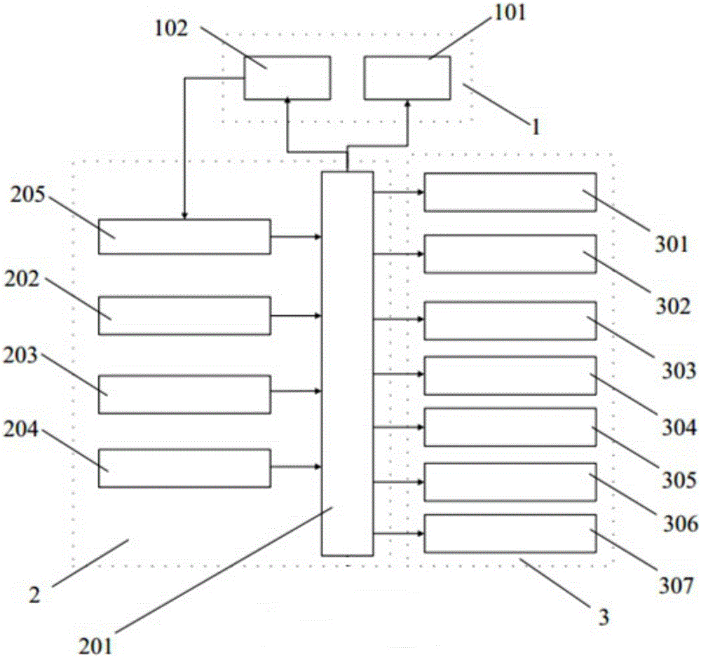
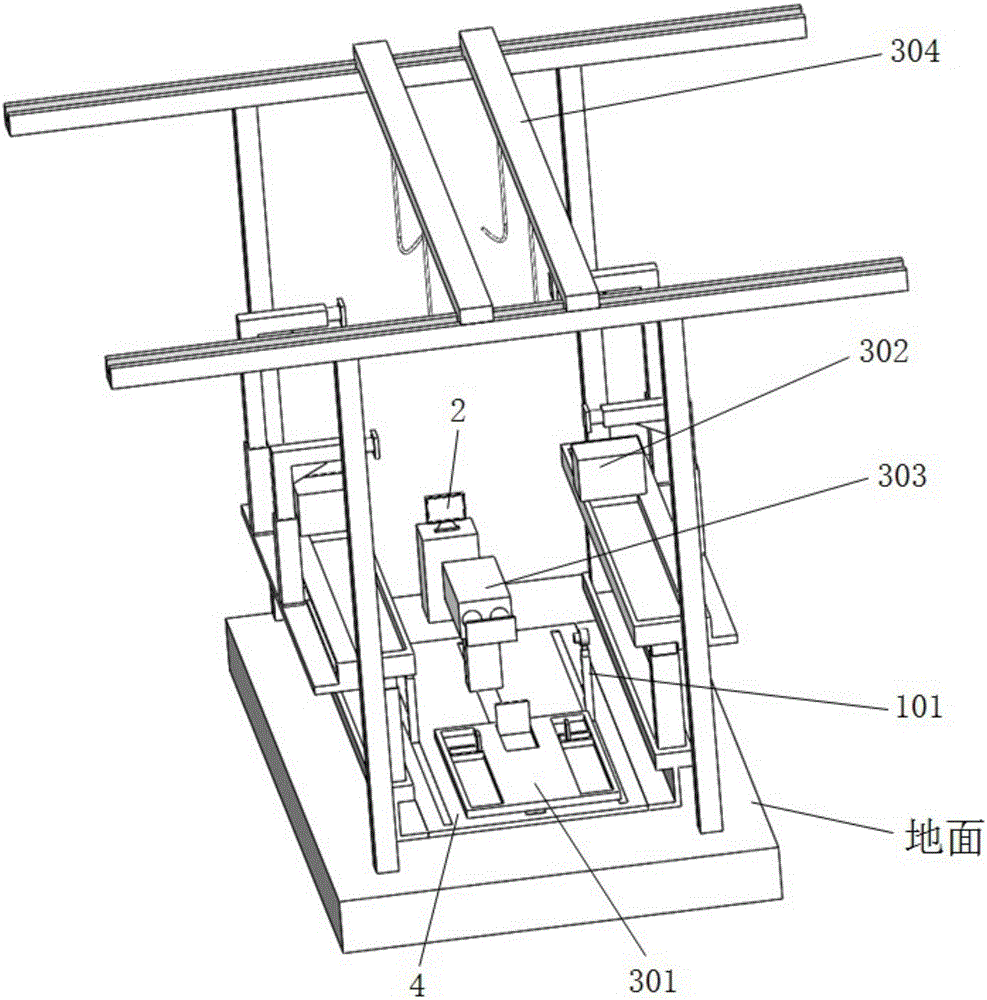
[0071] Such as Figure 1 to Figure 6b As shown, this embodiment provides an intelligent installation machine for hydraulic supports, including an installation execution system 3, a pin hole positioning assembly 1 and a control system 2, and the control system 2 is used for electrical connection with the installation execution system 3 and the pin shaft hole positioning assembly 1 For the operation of intelligent control installation execution system 3 and pin hole positioning component 1;

[0072] The installation execution system 3 includes a mobile platform assembly 301, a hoisting device 304, a clamping device, a manipulator assembly and a rear connecting rod push cylinder assembly; the mobile platform assembly 301 is used to move the hydraulic support base to the target position, and the hoisting device 304 is used to move the hydraulic The front connecting rod, rear connecting rod, top beam and cover beam of the bracket are moved to the target position, the manipulator as...

Embodiment 2

[0085] A method for installing a hydraulic support using the hydraulic support intelligent installation machine described in Embodiment 1, comprising the following steps,

[0086] (1) First, connect the cover beam ZJ4, the front connecting rod ZJ3 and the rear connecting rod ZJ2 of the hydraulic support to form an assembly for standby; install the column on the base of the hydraulic support for standby;

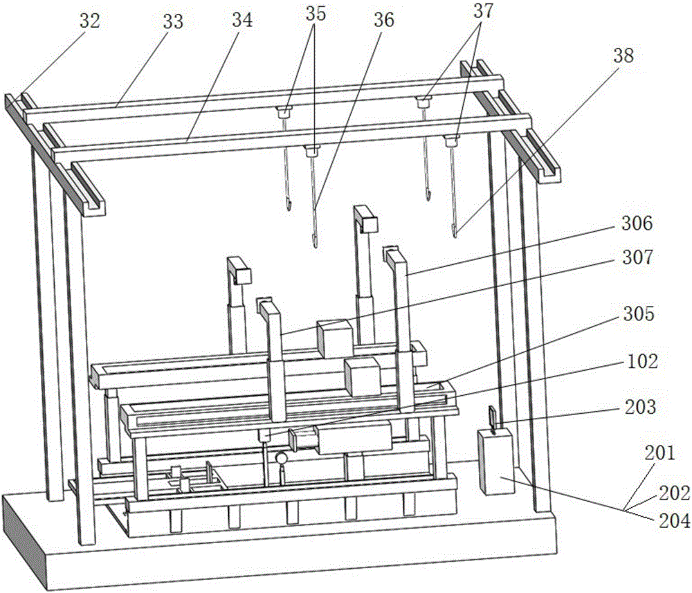
[0087] (2) Turn on the hydraulic support intelligent installation machine, the reference coordinate system is determined by the control system 2, the intelligent installation machine is in the initial position, that is, the mobile platform assembly 301 is located at the front end of the middle chute, and the laser light assembly 101 is located at the front end of the right chute 1. The projection board assembly 102 is located at the front end of the left chute, at this time, the initial position coordinates of each component of the intelligent installation machine in the refer...


PUM


Abstract

The invention relates to an intelligent installation machine for a hydraulic support and an application method of the intelligent installation machine. The intelligent installation machine comprises an installation implementation system, a hinge pin hole locating assembly and a control system. The control system is electrically connected with the installation implementation system and the hinge pin hole locating assembly and used for intelligently controlling operation of the installation implementation system and the hinge pin hole locating assembly. According to the intelligent installation machine for the hydraulic support and the application method of the intelligent installation machine, coordinate information of hinge-joint holes in a hydraulic support base, a front connection rod and a rear connection rod is obtained through a laser lamp module in the hinge pin hole locating assembly; centering of hinge-joint holes is completed by completing movement of the front connection rod and the rear connection rod in a preset coordinate system through the control system; and after hinge pins at specific positions are grabbed through mechanical arms in the installation implementation system, the hinge pins are inserted into the hinge-joint holes, so that installation of the front connection rod, the rear connection rod and the base as well as installation of a top beam and a shield beam are completed. By means of the intelligent installation machine, traditional hydraulic support installation modes are changed; manpower and material resources are saved; intelligentized control is achieved; installation precision is high; and installation efficiency is improved.

Description

technical field [0001] The invention relates to a hydraulic support intelligent installation machine and a method for using the same, belonging to the technical field of hydraulic support auxiliary equipment. Background technique [0002] The medium-thick coal seam has always been the main mining area of ​​coal mining. As the hydraulic support of important underground support equipment, it is of great significance to the safe and efficient mining of coal mines. With the continuous increase of coal seam mining thickness, the support height and adjustment range of hydraulic supports are also increasing. At present, some enterprises in my country have even developed extra-large mining height hydraulic supports with a maximum support height of 8.8 meters. The hydraulic support is required to have a strong bearing capacity, and it is generally welded by steel material components. Therefore, the hydraulic support has a large mass, and its components generally have a relatively lar...

Claims


Application Information

Patent Timeline
IPC IPC(8): E21D15/59
CPCE21D15/58
Inventor 曾庆良杨扬万丽荣尹广俊高魁东姜考王志文刘鹏李勇庆芦艳洁于鹏飞胡延清王通赵森庆邱志伟
Owner SHANDONG UNIV OF SCI & TECH
Why Eureka
Try Eureka