
A control method and system for a variable nozzle supercharger

A control method and supercharger technology, which are applied in the directions of machines/engines, engine components, gas turbine devices, etc., can solve the problems of variable nozzle supercharger overspeed risk, inability to effectively control supercharger response, etc., to avoid overspeed risk. Effect

Active Publication Date: 2018-02-23
GREAT WALL MOTOR CO LTD
View PDF3 Cites 0 Cited by
  • Summary
  • Abstract
  • Description
  • Claims
  • Application Information

AI Technical Summary

Problems solved by technology

[0004] At present, when controlling the variable nozzle supercharger, only the boost pressure demand, PID output and maximum supercharger position single value are used to control the variable nozzle supercharger. The position of the nozzle ring of the nozzle supercharger is limited, so that the response of the supercharger cannot be effectively controlled, and the variable nozzle supercharger has the risk of overspeed when the intake resistance or the pressure ratio of the supercharger becomes large

Method used


Image

  • A control method and system for a variable nozzle supercharger
  • A control method and system for a variable nozzle supercharger

Examples


Embodiment 1

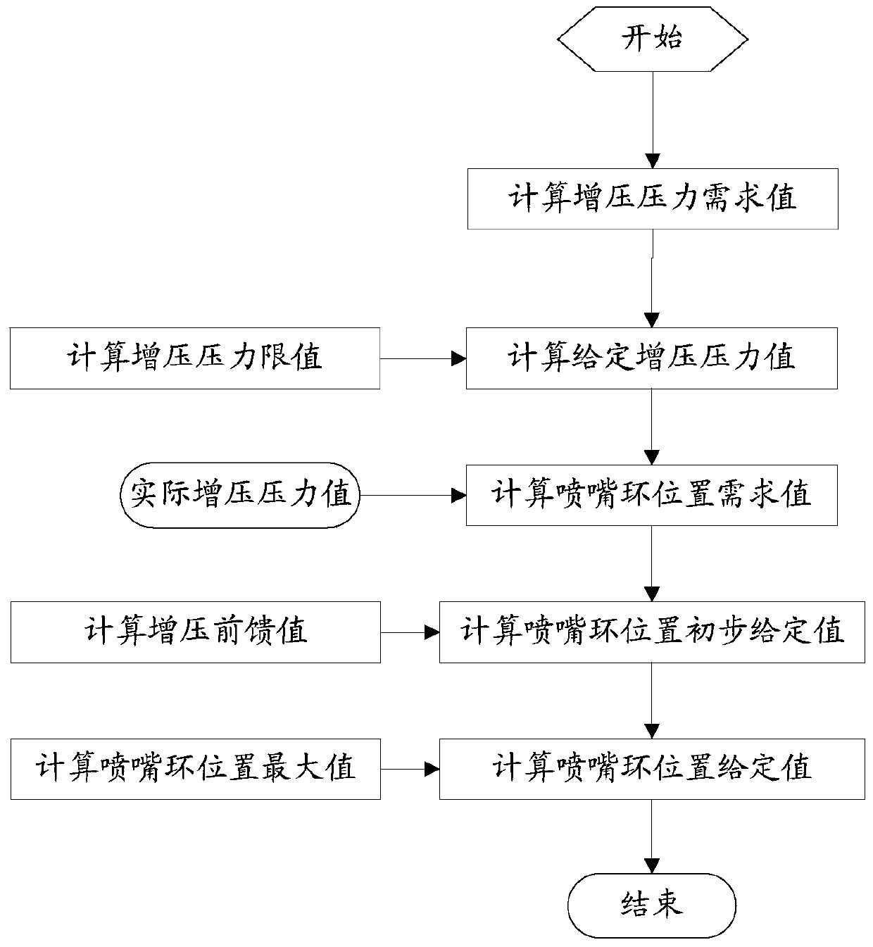
[0049] figure 1 It is a flow chart of a control method of a variable nozzle supercharger provided by the embodiment of the present application.

[0050] Such as figure 1 As shown, the control method of the variable nozzle supercharger provided in this embodiment includes the following steps:

[0051] S101: Calculate a boost pressure demand value.

[0052] According to the obtained engine speed and engine torque of the engine, the engine torque is the output torque of the engine, using the engine speed and engine torque to search on the corresponding first basic map, so as to obtain the boost pressure demand required by the engine value.

[0053] S102: Calculate a boost pressure limit.

[0054] According to the corrected intake air flow and the intake air temperature of the engine calculated by the electronic control unit of the engine according to the current power and other parameters, use the corrected intake air flow and intake air temperature in the second basic map co...

Embodiment 2

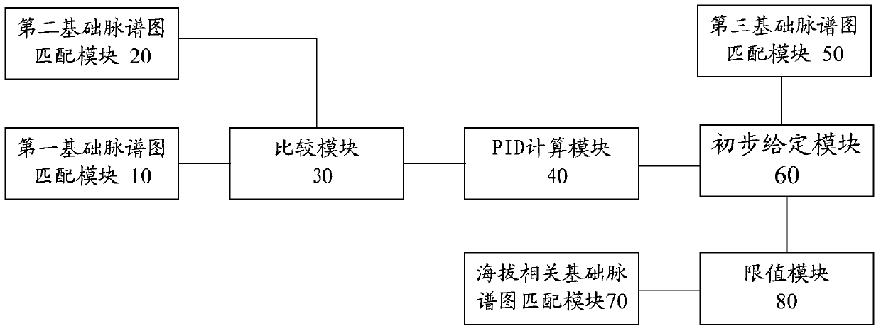
[0071] figure 2 It is a schematic diagram of a control system of a variable nozzle supercharger provided by another embodiment of the present application.

[0072] Such as figure 2 As shown, the control system of the variable nozzle supercharger provided in this embodiment includes a first basic map matching module 10, a second basic map matching module 20, a comparison module 30, a PID calculation module 40, a third basic A map matching module 50 , a preliminary setting module 60 , an altitude-related basic map matching module 70 and a limit value module 80 .

[0073] The first basic map matching module 10 is used to calculate a boost pressure demand value.

[0074] That is, according to the obtained engine speed and engine torque of the engine, a search is performed on the corresponding first basic map, so as to obtain the boost pressure demand value required by the engine.

[0075] The second base map matching module 20 is used to calculate a boost pressure limit.

[...


PUM


Abstract

The invention discloses a method and system for controlling a changeable nozzle pressurizer. The method includes: acquiring a given pressurizing pressure value according to a calculated pressurizing pressure demand value and a calculated pressurizing pressure limit value; performing PID calculation according to a difference between the given pressurizing pressure value and an actual measured pressurizing pressure value so as to acquire a nozzle ring position demand value of the changeable nozzle pressurizer; adding the nozzle ring position demand value and a pressurizing feed forward value to acquire a nozzle ring initial position given value; acquiring a nozzle ring position maximum value from an altitude associated basic pulse chart matching an altitude of a place where an engine is located according to the rotation speed and the torque of the engine; and using the nozzle ring position maximum value to perform limiting value treatment on the nozzle ring initial position given value so as to acquire a nozzle ring position given value, wherein the nozzle ring position given value is used for controlling a position of a nozzle ring of the changeable nozzle pressurizer. The method and the system can effectively control response of the changeable nozzle pressurizer, and then overspeed risk can be avoided when the intake resistance or the pressurizing pressure is increased.

Description

technical field [0001] The present application relates to the technical field of automobiles, and more specifically, to a control method and system for a variable nozzle supercharger. Background technique [0002] A turbocharger is an air pump that uses the residual energy in the engine's exhaust to work. The exhaust gas drives the turbine wheel assembly connected to the compressor wheel. When the turbocharger rotor turns, a large amount of compressed air is sent to the combustion chamber of the engine. Due to the increase of air entering the engine, more fuel is allowed to be injected into the engine, so that the engine can generate greater power under the condition of the same size, and can also improve combustion, reduce emissions and noise, and achieve environmental protection The purpose of energy saving. [0003] The variable nozzle supercharger has a set of nozzle blades with variable angles. The angle change of the nozzle blades is controlled by the ECU of the ele...

Claims


Application Information

Patent Timeline
Patent Type & Authority Patents(China)
IPC IPC(8): F01D17/16F02B37/24F02C6/12
CPCY02T10/12
Inventor 王亮王胜涛刘健曹付广王宗勃李庆峰林鑫
Owner GREAT WALL MOTOR CO LTD
Learn More