
Petroleum pipeline

A technology for oil pipelines and pipelines, which is used in pipeline protection, pipes, and pipelines through thermal insulation protection. The effect of preventing oil pipeline blockage, not easy to fall off, and prolonging service life

Inactive Publication Date: 2017-02-15
JIANGSU PROVINCE JINFENG PETROLEUM MACHINERY MFG CO LTD
View PDF0 Cites 3 Cited by
  • Summary
  • Abstract
  • Description
  • Claims
  • Application Information

AI Technical Summary

Problems solved by technology

[0002] Petroleum needs to be transported by oil pipelines in the process of exploration and development. The originally used oil pipelines have thin walls, poor structural strength, and do not have functions such as sound insulation, heat preservation, and fire prevention. In addition, due to the viscosity of oil itself, oil During the long-term transportation of the pipeline, oil tends to stick to the inner wall of the pipeline slowly, causing blockage of the oil pipeline and bringing inconvenience to the transportation of oil

Method used


Image

  • Petroleum pipeline
  • Petroleum pipeline

Examples


Embodiment Construction

[0010] The specific content of the present invention will be described in detail below in conjunction with the accompanying drawings and specific embodiments.

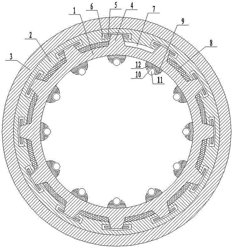
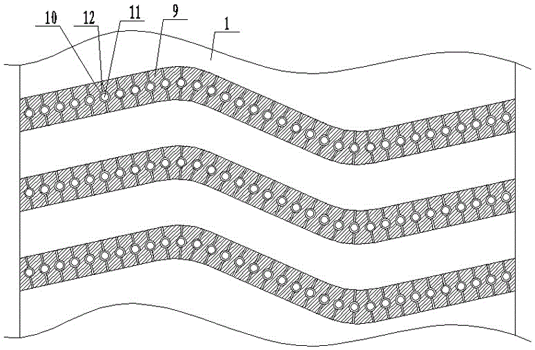
[0011] like figure 1 , figure 2 As shown, the oil pipeline includes: a pipeline body 1, a sound insulation layer 2 arranged outside the pipeline body 1, a fireproof outer layer 3 arranged outside the sound insulation layer 2, and several The trapezoidal reinforcing rib 4 is provided with clamping blocks 5 on both sides of one end of the trapezoidal reinforcing rib 4 extending into the sound-insulating layer 2, and the sound-insulating layer 2 is provided with a card that cooperates with the clamping block 5 The groove 6 is provided with a thermal insulation cavity 7 between the two adjacent trapezoidal reinforcing ribs 4, and the thermal insulation cavity 7 is filled with thermal insulation rock wool 8, and the inner wall of the pipeline body 1 is evenly spaced with Some S-shaped ribs 9 are evenly provided with some...


PUM


Abstract

The invention discloses a petroleum pipeline. The petroleum pipeline comprises a pipeline body, a sound insulation layer arranged on the outer side of the pipeline body and a fireproof outer layer arranged on the outer side of the sound insulation layer. A plurality of trapezoidal reinforcing convex ribs are evenly arranged on the outer side of the pipeline body. Clamping blocks are arranged on the two sides of the end, stretching into the sound insulation layer, of each trapezoidal reinforcing convex rib correspondingly. Clamping grooves matched with the clamping blocks are formed in the sound insulation layer. A heat preservation cavity is formed between every two adjacent trapezoidal reinforcing convex ribs and filled with heat preservation rock wool. A plurality of S-shaped convex edges are evenly arranged on the inner wall of the pipeline body at equal distance. A plurality of ball grooves are evenly formed in each S-shaped convex edge. A ball is arranged in each ball groove in a rolling manner. Lubrication channels are arranged at the positions, on the two sides of each ball groove, in each S-shaped convex edge, and one end of each lubrication channel communicates with the corresponding ball groove.

Description

technical field [0001] The invention relates to petroleum equipment, in particular to a petroleum pipeline. Background technique [0002] Petroleum needs to be transported by oil pipelines in the process of exploration and development. The originally used oil pipelines have thin walls, poor structural strength, and do not have functions such as sound insulation, heat preservation, and fire prevention. In addition, due to the viscosity of oil itself, oil During the long-term transportation of the pipeline, oil tends to slowly stick to the inner wall of the pipeline, causing blockage of the oil pipeline and bringing inconvenience to the transportation of oil. Contents of the invention [0003] The technical problem to be solved by the present invention is to provide an oil pipeline with good delivery effect. [0004] In order to solve the above-mentioned technical problems, the technical solution adopted in the present invention is: the petroleum pipeline, comprising: the p...

Claims


Application Information

Patent Timeline
Patent Type & Authority Applications(China)
IPC IPC(8): F16L9/14F16L55/033F16L57/04F16L59/04F16L55/24
CPCF16L9/14F16L55/0336F16L55/24F16L57/04F16L59/04
Inventor 郭峰王华陈旭
Owner JIANGSU PROVINCE JINFENG PETROLEUM MACHINERY MFG CO LTD
Learn More