
Pressure sensor

A pressure sensor and sensor component technology, applied in the direction of measuring fluid pressure, instruments, measuring fluid pressure through electromagnetic components, etc., can solve problems such as error signal analysis, signal transmission distortion, and changing the leakage current of pressure sensors

Active Publication Date: 2017-02-15
KISTLER HLDG AG
View PDF10 Cites 2 Cited by
  • Summary
  • Abstract
  • Description
  • Claims
  • Application Information

AI Technical Summary

Problems solved by technology

This makes it possible to increase the electrical contact resistance by several orders of magnitude from the mΩ range to the MΩ range and distorts the signal to the analysis unit, which leads to erroneous signal analysis
In general, it is also very important to ensure the electrical insulation of the signal conduction part at high temperatures, since this can change the leakage current of the components of the pressure sensor and distort the signal conduction
At high temperatures, different expansion coefficients of the components of the pressure sensor can also locally lead to mechanical stress
Finally, the components of the pressure sensor will age prematurely at high temperatures
This heat-induced mechanical stress and premature aging have a detrimental effect on the service life of the pressure sensor

Method used


Image

  • Pressure sensor
  • Pressure sensor
  • Pressure sensor

Examples


Embodiment Construction

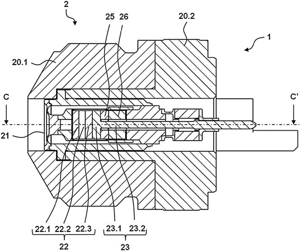
[0063] figure 1 with figure 2 Sections of two embodiments of the piezoelectric sensor 1 according to the invention are shown. These sections are shown along the longitudinal axis CC' of the piezo pressure sensor 1 after it has been inserted and assembled. The longitudinal axis CC', the vertical axis AA' and the horizontal axis BB' are perpendicular to each other. The direction along the longitudinal axis CC' is also referred to as the longitudinal direction, and the direction perpendicular to this longitudinal direction is also referred to as the radial direction. The vertical axis AA' and the horizontal axis BB' develop into a radial plane AB. The radial direction lies in this radial plane AB. The piezoelectric pressure sensor 1 and its components are substantially circular in cross-section with respect to the longitudinal axis CC'. The adjective "substantially" includes ±10% circular shape variations. However, within the understanding of the present invention, the pie...


PUM


Abstract

The invention relates to a pressure sensor (1) having a sensor group (2) and a analyzing unit (5), the sensor group (2) having a receiver (22) and an electrode assembly (23) (5) having a circuit board (51), the base material of the circuit board (51) being electrically insulated, and the circuit board (51) is electrically connected to the analysis unit (5) (51) having a high temperature region (51.1) toward the sensor group (2) and a normal temperature region (51) of the back sensor group (2), the circuit board (51) having a specific through resistance greater than or equal to 1015 Omega cm at room temperature.

Description

technical field [0001] The invention relates to a pressure sensor according to the preambles of the independent claims. Background technique [0002] Pressure sensors are well known and widely used. The cylinder pressure present in the pressure chamber is detected as a function of crankshaft position or time as a function of the crankshaft position or as a function of the pressure indication of the internal combustion engine by means of piezoelectric pressure sensors. Internal combustion engines include four-stroke engines and two-stroke engines, such as Otto engines, diesel engines, Wankel engines, and the like. In marine diesel engines, the cylinder pressure can be monitored permanently with the aid of pressure sensors. Pressure changes are detected quickly with piezoelectric pressure sensors, typically in the range of 150 to 250 bar, but also have pressure peaks of 500 bar and higher during pre-ignition and engine detonation. Piezoelectric pressure sensors are also use...

Claims


Application Information

Patent Timeline
Patent Type & Authority Applications(China)
IPC IPC(8): G01L9/08
CPCG01L9/08G01L19/06G01L19/146G01L19/148G01L23/10G01L23/26G01L19/0084G01L19/04G01L23/222G01D11/245G01L23/225F02D35/023G01L1/18G01L9/0052
Inventor R·布克M·吉格U·涅德尔曼
Owner KISTLER HLDG AG
Learn More