
PCIE device hot-plug design method

A design method and hot-swappable technology, applied in the field of computer communication technology, can solve problems such as system downtime, inability to realize uninterrupted system operation and maintenance, and affecting system operation and maintenance efficiency, so as to achieve the effect of reliability

Inactive Publication Date: 2017-02-15
ZHENGZHOU YUNHAI INFORMATION TECH CO LTD
View PDF5 Cites 6 Cited by
  • Summary
  • Abstract
  • Description
  • Claims
  • Application Information

AI Technical Summary

Problems solved by technology

[0003] In the current method of using PCIE devices, when a PCIE device in the system fails, since the PCIE device does not support online hot-swap replacement, the faulty device must be replaced after the main board is shut down, and the uninterrupted operation and maintenance of the system cannot be realized. The current method of using PCIE devices has major disadvantages: First, the online maintenance of the system cannot be guaranteed. If the PCIE device fails, it needs to be shut down, which seriously affects the operation and maintenance efficiency of the system; When the equipment fails, it may cause the overall high-speed signal and power supply of the system to be abnormal, resulting in system downtime, and the reliability of the system cannot be guaranteed
In view of the low operation and maintenance efficiency and insufficient system reliability in the current use of PCIE equipment, in order to ensure the fast, efficient and stable operation of the server system, it is particularly important to realize the online hot-swap design during the use of PCIE equipment in the actual server system, and Become one of the key factors that determine the advantages of server reliability

Method used


Image

  • PCIE device hot-plug design method

Examples


Embodiment Construction

[0022] The present invention will be further described below in conjunction with specific embodiments according to the accompanying drawings of the description:

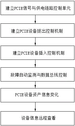
[0023] 1. Using a high-speed FPGA chip, establish a PCIE signal and power supply link control unit, connect the 16-bit data transceiver bus, PCIE synchronous clock, and PCIE 12V / 3.3V power supply signal on the motherboard side to the unit, and connect the PCIE device to the unit at the same time. The PCIE 16-bit data transceiver bus, PCIE synchronous clock, and PCIE 12V / 3.3V power supply signal are also connected to the unit.

[0024] 2. Establish a PCIE device unplugging control mechanism. On the main board of the server, set the PCIE device unplugging action notification button. When the PCIE device is to be replaced, the user triggers the PCIE device unplugging action notification button, and the PCIE signal and power supply link control unit, After receiving the action signal, cut off the PCIE synchronous clock b...


PUM


Abstract

The invention discloses a PCIE device hot-plug design method. The PCIE device hot-plug design method comprises the steps of establishing a PCIE signal and power supply link control unit; connecting a main-board end and a PCIE signal of a PCIE device to the PCIE signal and power supply link control unit; carrying out active and automatic isolation for key signals in the link to realize PCIE link state control and an independent control section before and after the plugging of the PCIE device; and performing PCIE hot-plug operation protection in a targeted manner to guarantee system reliability. The PCIE device hot-plug design method can realize PCIE device hot-plug design conveniently, and not only can achieve the reliability requirement, but also can realize a high-efficiency requirement, and reliability and stability of the server system.

Description

technical field [0001] The present invention relates to the technical field of computer communication, in particular to a PCIE device hot-swapping design method to solve the problems of low operation and maintenance efficiency and insufficient system reliability in the current use of PCIE devices. In order to ensure the fast, efficient and stable operation of the server system, In the process of using the PCIE device in the actual server system, it is particularly important to realize the online hot-swap design, and it has become one of the key elements to determine the reliability of the server. Background technique [0002] In the current server system, for the support of PCIE devices, the method of direct connection between the motherboard and the PCIE device is generally adopted, that is, the high-speed signal and power supply of the PCIE device are directly connected to the output end of the motherboard, and there is no auxiliary link in the middle. The current PCIE devi...

Claims


Application Information

Patent Timeline
IPC IPC(8): G06F13/40
CPCG06F13/4081
Inventor 刘涛
Owner ZHENGZHOU YUNHAI INFORMATION TECH CO LTD
Learn More