Heat exchange structure with annular fins and heat dissipation device with heat exchange structure

A technology of heat exchange structure and heat dissipation device, which is applied to electrochemical generators, electrical components, circuits, etc., can solve the problems of excessive weight of heat dissipation fins, complicated processes, and large volume, and achieves reduction of material cost and manufacturing cost, Small size and weight, enhanced heat transfer effect

Active Publication Date: 2017-02-15
SHANGHAI UNIV OF ENG SCI
View PDF8 Cites 7 Cited by
  • Summary
  • Abstract
  • Description
  • Claims
  • Application Information

AI Technical Summary

Problems solved by technology

The heat dissipation fins of this patent are prepared by extrusion process, which is relatively complex and time-consuming, and the heat dissipation f

Method used


Image

  • Heat exchange structure with annular fins and heat dissipation device with heat exchange structure
  • Heat exchange structure with annular fins and heat dissipation device with heat exchange structure
  • Heat exchange structure with annular fins and heat dissipation device with heat exchange structure

Examples


Embodiment 1

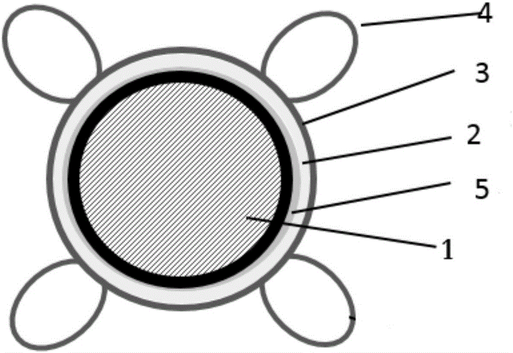
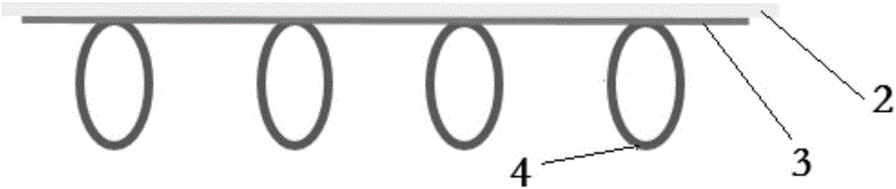
[0044] A heat exchange structure with annular fins, the structure of which is as follows figure 1 As shown, the heat exchange structure is used to enhance the heat dissipation capability of the heat-generating device to the external environment. The heat-exchange structure includes the heat-generating device 1, the interface heat-conducting adhesive layer 5, the wrapping tape 2 and the heat-conducting tape 3 from the inside to the outside, and the heat-conducting tape 3 is provided with 4 annular fins 4, wherein the material of the winding belt 2, the conductive belt 3 and the annular fin 4 is aluminum, the conductive belt 3 and the winding belt 2 are welded and connected, and the material of the interface thermally conductive adhesive layer 5 is EA9189. Among them, the structure of the heat conduction belt used in the heat exchange structure is as follows: figure 2 , image 3 As shown, the heat conduction tape 3 can be a continuous heat conduction tape or a disconnected hea...

Embodiment 2

[0046] A heat exchange structure with annular fins, the structure of which is as follows Figure 4 As shown, the heat exchange structure is to directly bend the conductive belt 3 to form four annular fins 4, which are fixed on the heat generating device 1, and the shape of the annular fins 4 is as follows: Figure 5 , Figure 6 As shown, the annular fin 4 can be elliptical or linear, and the shape of the annular fin 4 can be arbitrarily selected according to the requirement of heat exchange capacity, as long as it extends outward on the basis of the conduction belt 3 Can.

Embodiment 3

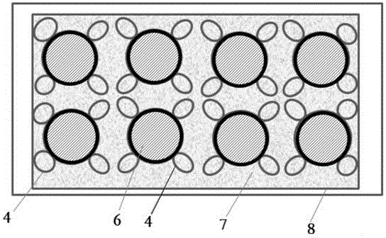
[0048] A heat exchange structure with annular fins, its structure is similar to Embodiment 1, the difference is that there are 8 annular fins in this embodiment, the specific structure is as follows Figure 7 shown.


PUM

PropertyMeasurementUnit
Thermal conductivityaaaaaaaaaa
Phase transition temperatureaaaaaaaaaa
Thermal conductivityaaaaaaaaaa

Abstract

The invention relates to a heat exchange structure with annular fins, which is used for improving heat dissipation capability of a heat generation device on an external environment. The heat exchange structure comprises the heat generation device and a heat conduction tape, wherein the heat conduction tape is wound around the heat generation device, and one group or multiple groups of annular fins are arranged at the outer side of the heat conduction tape. The invention also relates to a heat dissipation device having the heat exchange structure with the annular fins. The heat dissipation device comprises a box body and multiple groups of heat exchange structures, the multiple groups of heat exchange structures are arranged in the box body, a heat absorption material is arranged between the box body and the heat exchange structures, and the heat absorption material comprises one of a phase change material, an elastic encapsulating material or insulation heat conduction oil. Compared with the prior art, the heat exchange structure with the annular heat conduction fins has the advantages of excellent heat transfer improvement effect, good impact buffer effect, structure flexibility, light weight, small size and the like, and the composite heat dissipation device is excellent in heat dissipation performance.

Description

technical field [0001] The invention relates to the technical field of power battery heat dissipation, in particular to a heat exchange structure with annular fins and a heat dissipation device with the heat exchange structure. Background technique [0002] Power batteries such as lithium-ion batteries have high energy density, small size, and long cycle life. They have great application potential and market in motorcycles and electric vehicles. However, due to the temperature rise of lithium-ion batteries during the charging and discharging process, their performance and cycle life are affected. Excessively high temperatures may even cause thermal runaway, expansion and rupture of the shell, resulting in accidents such as spontaneous combustion and explosion. However, the temperature of conventional lithium cobalt oxide batteries needs to be controlled. Within 50 degrees Celsius to avoid thermal runaway and improve safety. Although the working temperature of the lithium ir...

Claims


Application Information

Patent Timeline
IPC IPC(8): H01M10/613H01M10/6551H01M10/6561H01M10/6567
CPCH01M10/613H01M10/6551H01M10/6561H01M10/6567Y02E60/10
Inventor 张恒运王兆强邢彦锋夏欣江磊
Owner SHANGHAI UNIV OF ENG SCI
Why Eureka
Try Eureka