
Method for realizing motor accurate control by using linear Hall sensors

A linear Hall, precise control technology, applied in the electromechanical field, can solve the problems of high cost of photoelectric encoder disk, inability to provide angle information, complex motor structure, etc., to avoid the problem of lost steps, fine position control, small size and weight Effect

Inactive Publication Date: 2017-02-15
刘世超
View PDF2 Cites 4 Cited by
  • Summary
  • Abstract
  • Description
  • Claims
  • Application Information

AI Technical Summary

Problems solved by technology

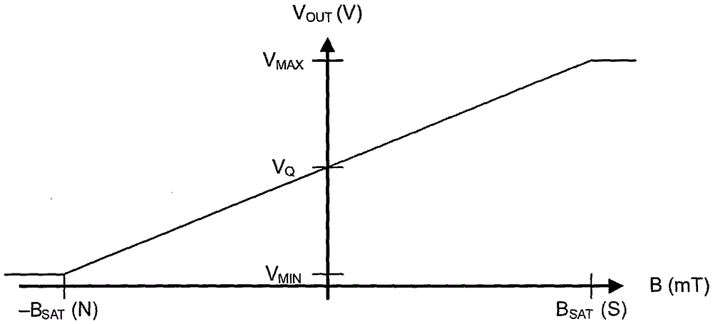
[0004] For example, a typical 3 switch-type Hall sensors are arranged in a 120-degree layout, which divides a cycle into 6 intervals, but cannot provide finer angle information in one interval, although it is assumed that the rate of change of the motor speed is low. Under normal circumstances, it can be estimated based on the motor speed and the current time, but when the speed is very low or the load changes greatly, the estimation accuracy will be significantly reduced, resulting in the disadvantage of trembling or small starting torque
[0005] In order to obtain a fine and accurate rotor phase angle and determine the rotor position, the industry usually uses a servo motor combined with a photoelectric encoder, but its disadvantage is that the cost of the photoelectric encoder is high, and the addition of photoelectric encoder components makes the entire motor structure complex

Method used


Image

  • Method for realizing motor accurate control by using linear Hall sensors
  • Method for realizing motor accurate control by using linear Hall sensors
  • Method for realizing motor accurate control by using linear Hall sensors

Examples


Embodiment Construction

[0028] The present invention will be further described below in conjunction with the accompanying drawings and examples, and the contents of the examples are not intended to limit the protection scope of the present invention.

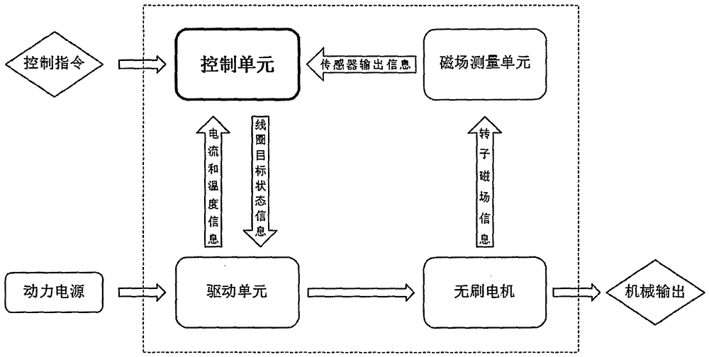
[0029] A specific embodiment of the present invention is structured as Figure 4 As shown, it includes a brushless motor (1), a magnetic field measurement unit (5), a control unit (2), and a drive unit (3).

[0030] The above-mentioned magnetic field measuring unit mainly includes a circuit board and a linear Hall sensor (4). The circuit board and the stator are fixed on the machine base. The stator includes an iron core, a coil winding, and a bearing. The stator cooperates with the rotor through the bearing. The rotor includes a casing, a permanent magnet, and a shaft.

[0031] Example methods such as figure 1 , with the control unit as the core of the entire system, the control unit accepts the control commands input from the outside, and receives...


PUM


Abstract

The invention relates to a method for realizing motor accurate control by using linear Hall sensors, and belongs to the electromechanical field. The method comprises a control unit, a magnetic field measuring unit, a driving unit and a brushless motor, wherein the control unit is a core of a whole system; the control unit accepts control commands input from outside, receives information which is output by the magnetic field measuring unit and obtained by measurement of a rotor magnetic field of the brushless motor through linear Hall sensors in the measuring unit, and receives temperature and current information fed back by the driving unit at the same time; the control unit calculates target state information of a brushless motor winding based on the information, and transmits the target state information to the driving unit; and the driving unit drives the brushless motor to output in order to realize dynamic closed-loop control. Compared with a conventional inductive brushless motor, the method has the advantages that precise phase angle information is obtained under the condition of not changing a structure or increasing the cost, and motor accurate control is realized. Compared with a servo motor, the method has the advantages that motor accurate control is realized, and the cost is lowered at the same time.

Description

technical field [0001] The invention relates to the electromechanical field, in particular to a method for realizing precise control of a motor by using a linear Hall sensor. Background technique [0002] With the continuous upgrading of my country's manufacturing industry and the rapid development of manufacturing technology, there is a large demand for high-quality and precise control drive technology in the industry. The traditional methods include: brushless motors with sense, servo motors, stepping motors and other technical methods, but there are some shortcomings. The invention provides a motor position closed-loop control technical method with high control precision and low cost. [0003] Traditional sensory brushless motors use switch-type Hall sensors, such as image 3 As shown, the signal is output only after the direction of the magnetic field changes. Although electronic commutation can be realized, the hysteresis is high and the phase of the motor rotor is relat...

Claims


Application Information

Patent Timeline
IPC IPC(8): H02P6/17
Inventor 刘世超
Owner 刘世超
Learn More