
Film capacitor

A film capacitor, capacitor technology, applied in the direction of film/thick film capacitors, capacitors, fixed capacitor electrodes, etc.

Active Publication Date: 2017-02-15
PANASONIC INTELLECTUAL PROPERTY MANAGEMENT CO LTD
View PDF4 Cites 8 Cited by
  • Summary
  • Abstract
  • Description
  • Claims
  • Application Information

AI Technical Summary

Problems solved by technology

In addition, the conventional film capacitor is configured such that the portion closest to the positive external terminal portion 92A2 provided on the positive bus bar 92A for external connection and the negative external terminal portion 92B2 provided on the negative bus bar 92B for external connection, The capacitor element 91 is not arranged, and only the molding resin 96 is arranged

Method used


Image

  • Film capacitor
  • Film capacitor
  • Film capacitor

Examples


Embodiment Construction

[0018] Hereinafter, the configuration and manufacturing method of the film capacitor in the first embodiment will be described with reference to the drawings.

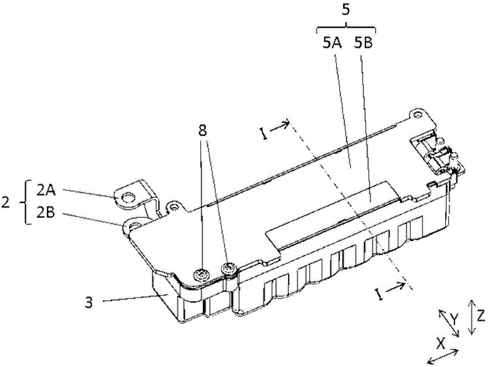
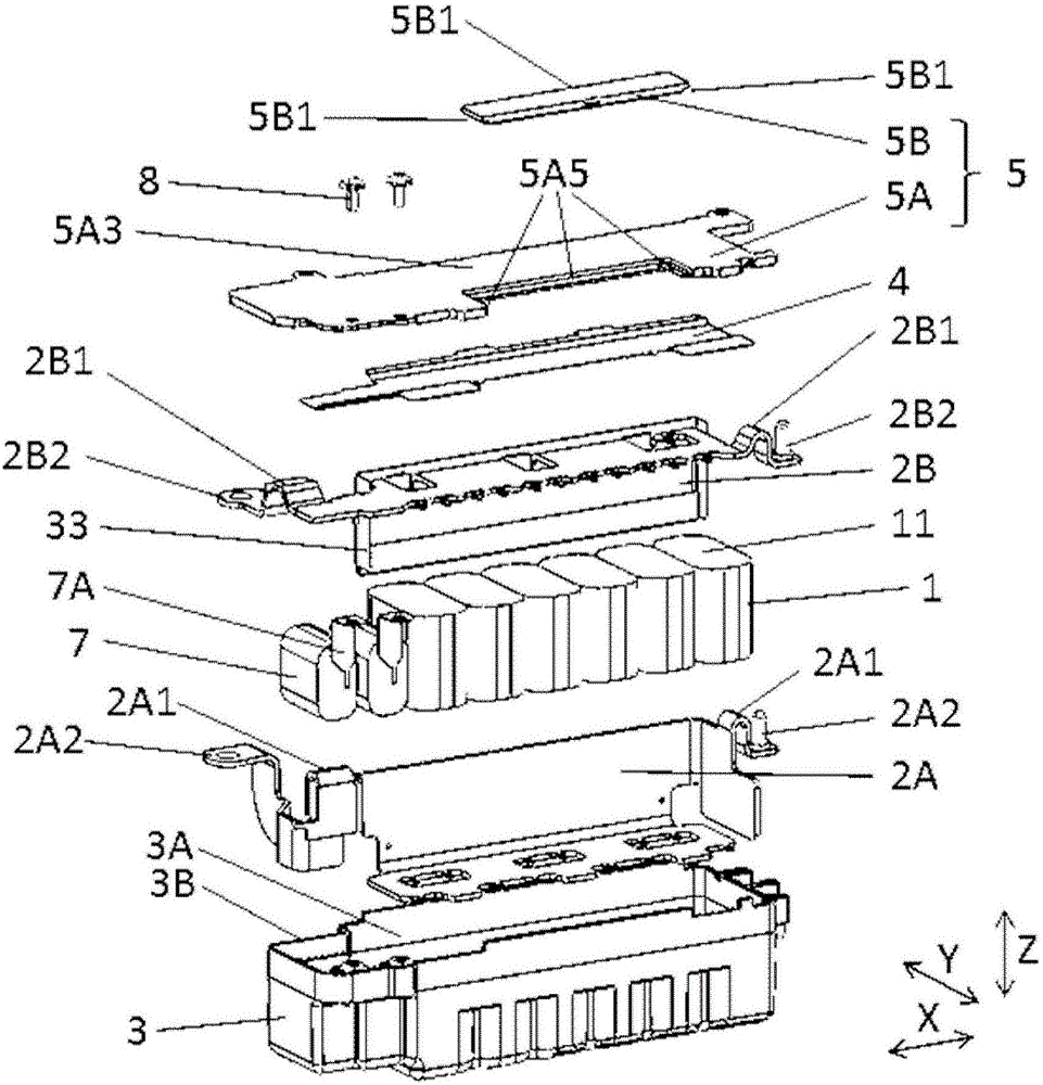
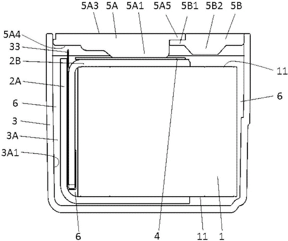
[0019] figure 1 is a perspective view of the film capacitor of the first embodiment, figure 2 It is an exploded perspective view of the main part of a film capacitor. also, image 3 yes figure 1 Sectional view at cutting line I-I of .

[0020] In this embodiment, the film capacitor includes six capacitor elements 1 for current smoothing. Metallization electrodes 11 are formed at both ends of each capacitor element 1 . Here, the configuration of the capacitor element 1 will be described in detail. The capacitor element 1 has two opposite end surfaces and a side surface connecting the two end surfaces, and has a flat shape (a shape having two flat surfaces and two curved surfaces) when viewed from the end surfaces. In addition, the capacitor element 1 includes a pair of metalized thin films. The metallized fil...


PUM


Abstract

This film capacitor is configured such that: the film capacitor is provided with a capacitor element having a metallikon electrode formed at an end portion, a bus bar connected to the metallikon electrode, a case having a housing section for housing the capacitor element and the bus bar, a cover member covering an opening of the housing section, and a heat conducting member that is disposed between the bus bar and the cover member; the cover member has a protruding section on the side facing the heat conducting member; the protruding section is in contact with the heat conducting member; and the heat conducting member is in contact with the bus bar. With such configuration, the film capacitor having further improved heat dissipating characteristics can be provided.

Description

technical field [0001] The present invention relates to a film capacitor in which a capacitor element is accommodated in a case. Background technique [0002] In recent years, film capacitors mounted in electric equipment, electronic equipment, industrial equipment, automobiles, etc. have been required to improve the reliability of film capacitors by releasing heat generated during charge and discharge. [0003] For example, Patent Document 1 discloses a film capacitor including a plurality of capacitor elements and bus bars connected to the capacitor elements, and a heat dissipation device is provided at the portion closest to the terminal portion for external connection provided on the bus bars. Cooling unit with superior performance than other parts. It will be described in detail below. [0004] Figure 6 is a perspective view showing the configuration of a conventional film capacitor, Figure 7 It is a plan view of the state after removing the positive electrode bus ...

Claims


Application Information

Patent Timeline
IPC IPC(8): H01G2/08H01G2/10H01G4/224H01G4/228
CPCH01G2/04H01G2/08H01G2/106H01G4/224H01G4/228H01G4/258H01G4/38Y02T10/70H01G4/002H01G4/005H01G4/33
Inventor 小山雄基尾崎晃弘
Owner PANASONIC INTELLECTUAL PROPERTY MANAGEMENT CO LTD
Learn More