
Plane warehouse location management system based on rfid floor mat

A management system and storage location technology, applied in the field of storage location identification, can solve problems such as poor use flexibility, heavy workload, and easy breakage, and achieve the effect of improving use flexibility, reducing construction workload, and avoiding resource consumption.

Active Publication Date: 2019-01-22
MESNAC
View PDF14 Cites 0 Cited by
  • Summary
  • Abstract
  • Description
  • Claims
  • Application Information

AI Technical Summary

Problems solved by technology

[0003] In the traditional warehousing system, there is often a large randomness in the storage of items, which causes problems such as slow process speed, low efficiency and chaotic management
In the existing flat inventory storage mode, it is often used as a location identification method by writing the name of the location on the location, pasting a paper barcode, etc., and checking and identifying the location through manual observation or a barcode reader. This often results in greatly reduced operating speed and warehouse operating efficiency
RFID technology can greatly improve the identification efficiency. In the existing RFID storage management system, the buried RFID storage label is used on the flat storage location, which is set in the installation slot opened on the ground to avoid repeated grinding by electric forklifts. For details, please refer to the buried RFID cargo location label disclosed in the application number 201120346822.7. The buried RFID cargo location label needs to be installed on the ground, resulting in a large workload and affecting RFID. The success rate of the reader to read and write RFID cargo location tags; punching and slotting on the warehouse floor (especially the floor of the multi-layer warehouse) will damage the ground structure; when the floor material is metal, it will be shielded after drilling and installation The RFID cargo location label signal makes it impossible to recognize the RFID cargo location label; and in the flat warehouse location management system, the buried RFID cargo location label is generally in a fixed warehouse location, and cannot follow the location when the location is re-divided or the location changes The storage location changes and changes flexibly, resulting in poor flexibility of use

Method used


Image

  • Plane warehouse location management system based on rfid floor mat
  • Plane warehouse location management system based on rfid floor mat
  • Plane warehouse location management system based on rfid floor mat

Examples


Embodiment Construction

[0019] In order to make the purpose, technical solutions and advantages of the embodiments of the present invention clearer, the technical solutions in the embodiments of the present invention will be clearly and completely described below in conjunction with the drawings in the embodiments of the present invention. Obviously, the described embodiments It is a part of embodiments of the present invention, but not all embodiments. Based on the embodiments of the present invention, all other embodiments obtained by persons of ordinary skill in the art without making creative efforts belong to the protection scope of the present invention.

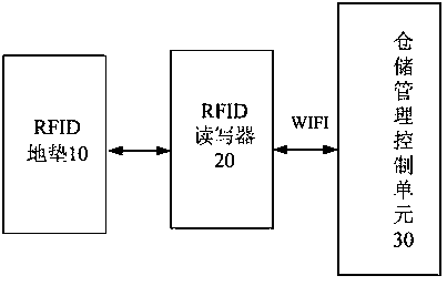
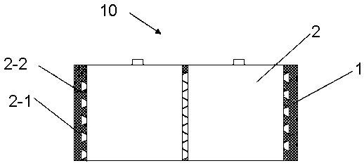
[0020] Such as figure 1 As shown, the present embodiment relates to a plane warehouse location management system based on RFID floor mats, including RFID floor mats 10, RFID reader-writer 20 and warehouse management control unit 30, wherein as figure 2 As shown, the RFID floor mat 10 includes a non-slip isolation layer 1, a compression-resi...


PUM


Abstract

The present invention relates to a flat storehouse location management system based on an RFID floor mat, which is characterized in that it includes an RFID floor mat, an RFID reader-writer, and a warehouse management control unit; The anti-pressure and wear-resistant layer, and the RFID location label embedded in the anti-pressure and wear-resistant layer or set at the bottom of the anti-pressure and wear-resistant layer, the non-slip isolation layer is closely attached to the ground; the RFID reader reads the RFID location label , the warehouse management control unit communicates with the RFID reader. The floor mat is easy to install and use, and it can be laid directly on the ground to avoid damage to the ground structure caused by slotting on the ground; the floor mat is directly laid on the ground of different materials, which expands its scope of use; it can be flexibly changed according to the warehouse location Adjust the RFID floor mat to improve the flexibility of use; through the communication connection between the RFID reader and the warehouse management control unit, the verification of the RFID cargo label information can be realized, and the cargo can be forked accurately to avoid resource consumption and improve work efficiency.

Description

technical field [0001] The invention relates to the technical field of storage location identification, in particular to a flat storage location management system based on RFID floor mats. Background technique [0002] Radio frequency identification technology (Radio Frequency Identification, RFID), radio frequency identification technology is a technology that uses radio frequency signals to achieve non-contact information transmission through spatial coupling (alternating magnetic field or electromagnetic field) and achieve identification purposes through the transmitted information. RFID radio frequency identification is a non-contact automatic identification technology. It automatically identifies the target object and obtains relevant data through radio frequency signals. The identification work does not require manual intervention and can work in various harsh environments. RFID technology can identify high-speed moving objects and can identify multiple electronic tags...

Claims


Application Information

Patent Timeline
Patent Type & Authority Patents(China)
IPC IPC(8): A47G27/02G06K19/07G06Q10/08B32B9/04B32B5/18B32B25/04B32B3/30B32B3/08
CPCA47G27/0206A47G27/0281A47G27/0293B32B3/08B32B3/30B32B5/18B32B9/043B32B25/045B32B2262/00B32B2307/744G06K19/07G06Q10/087
Inventor 佟强陈海军董兰飞姚永祁海波
Owner MESNAC
Learn More