Heart rate detection method and system
A detection method and heart rate technology, applied in the detection field, can solve the problems of high power consumption, easy error, unstable detection device, etc., and achieve the effect of avoiding inaccurate heart rate signals and improving detection accuracy.
- Summary
- Abstract
- Description
- Claims
- Application Information
AI Technical Summary
Problems solved by technology
Method used
Image
Examples
Embodiment 1
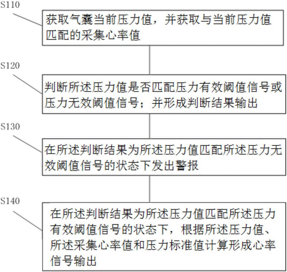
[0067] figure 1 This is a flowchart of a heart rate detection method provided in the first embodiment of the present invention. This embodiment is applicable to heart rate detection. The method can be executed by hardware equipped with corresponding software and specifically includes the following steps:
[0068] Step S110: Obtain the current pressure value of the airbag, and obtain the collected heart rate value matching the current pressure value; the side of the airbag one is fixedly connected to the detection system or the detection device body, and the other side is close to the skin of the human body, and the pressure value of the airbag is actually The upper detection system or the time pressure value of the detection device body on the human body surface. The detection system or the detection device may adopt the sound pressure detection method to obtain the collected heart rate value.
[0069] Furthermore, the skin on the surface of the human body can be the skin correspon...
Embodiment 2
[0079] Normally the human body is in a normal state, and the heart rate changes slowly and is in a relatively stable state. When the human body is in motion, the heart rate changes rapidly, and the heart rate signal is important for the user to judge whether the human body can continue to exercise in the current state. Therefore, the acquisition frequency of the heart rate value under exercise is greater than the frequency acquisition in the normal state, and the frequency acquisition in the exercise state is usually real-time acquisition. But the power consumption of real-time acquisition will be very large.
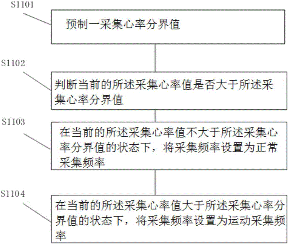
[0080] As a further preferred embodiment, in the above-mentioned heart rate detection method, in step S110, obtaining the current pressure value of the airbag and obtaining the collected heart rate value matching the current pressure value further includes:
[0081] Step S1101: Pre-make a collection of heart rate cut-off values;
[0082] Step S1102, determine whether the curr...
Embodiment 3
[0087] When the human body is in motion, the detection system or the detection device body and the human skin surface move relative to each other, and sometimes the pressure value may be momentarily low, and then a false alarm may occur, in order to overcome this defect.
[0088] As a further preferred embodiment, in the above-mentioned heart rate detection method, in step S130, issuing an alarm in a state where the pressure value matches the pressure invalid threshold signal includes:
[0089] Step S1301, in a state where N pressure values matching the pressure invalid threshold signal are continuously obtained within a predetermined time, determine that the current collected heart rate value is invalid;
[0090] Step S1302, issue the alarm.
[0091] The alarm signal will be sent out only when the N pressure values matching the pressure invalid threshold signal are continuously obtained to avoid false alarms.
[0092] As a further preferred embodiment, where N is a positive integer...
PUM
 Abstract
Description
Claims
Application Information
 - R&D
- Intellectual Property
- Life Sciences
- Materials
- Tech Scout
- Unparalleled Data Quality
- Higher Quality Content
- 60% Fewer Hallucinations
Browse by: Latest US Patents, China's latest patents, Technical Efficacy Thesaurus, Application Domain, Technology Topic, Popular Technical Reports.
© 2025 PatSnap. All rights reserved.Legal|Privacy policy|Modern Slavery Act Transparency Statement|Sitemap|About US| Contact US: help@patsnap.com


