Impinging stream reaction and separation integration device and impinging stream reaction and separation integration method for liquid-liquid reaction system

A technology of impinging flow reaction and liquid-liquid reaction, which is applied in the field of reactors, can solve problems such as reactor dead zones, achieve the effect of reducing failure rate, reducing process flow, and realizing timely separation

Inactive Publication Date: 2017-02-22
李泽深
View PDF5 Cites 3 Cited by
  • Summary
  • Abstract
  • Description
  • Claims
  • Application Information

AI Technical Summary

Problems solved by technology

For example, the patent "No-rotation vertical circulation impingement flow reactor" (patent number: CN200720083472.3) promotes the mutual impact of fluids through the action of the propeller in the guide tube to achieve the purpose of intensified mixing; the patent CN100364656C is set in the reactor shell With two facing guide cylinders, the liquid flows through the guide cylinders on both sides through the drive of the pump, and then collides at the center, but the reactor is prone to cause dead zones on both sides
The above-mentioned patent strengthens the impact of two streams of fluids, but pays less attention to the internal dead zone of the reactor and the multi-impact enhanced mixing process, and it is only used as a reactor, and additional separation devices need to be designed in industrial applications

Method used


Image

  • Impinging stream reaction and separation integration device and impinging stream reaction and separation integration method for liquid-liquid reaction system
  • Impinging stream reaction and separation integration device and impinging stream reaction and separation integration method for liquid-liquid reaction system
  • Impinging stream reaction and separation integration device and impinging stream reaction and separation integration method for liquid-liquid reaction system

Examples


Embodiment Construction

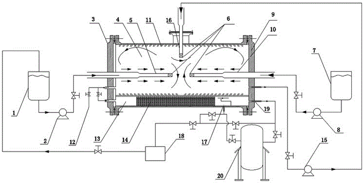
[0026] combined with Figure 1-6 , to further describe the present invention:

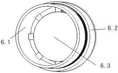
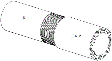
[0027] An impingement flow reaction separation integrated device for a liquid-liquid reaction system mentioned in the present invention includes a device cylinder with a horizontal structure, three storage tanks and three booster pumps, and the device cylinder is divided into The reaction chamber 4 and the separation chamber 13 are provided with three main guide tubes in the reaction chamber 4, and the three guide tubes are connected to the head and the flange in a welded manner; wherein the first main guide tube 5 and the second guide tube The main flow guide tube 10 is arranged facing the horizontal axis, and the circulation main flow guide tube 16 is arranged on the upper side of the middle part of the device cylinder to realize the circulation of the two-phase liquid for multiple collisions. The ports of the three flow guide tubes are all equipped with guide vanes 6 , and a corrugated plate 14...


PUM


Abstract

The invention relates to an impinging stream reaction and separation integration device and an impinging stream reaction and separation integration method for a liquid-liquid reaction system. The impinging stream reaction and separation integration device comprises a device barrel body, three storage tanks and three booster pumps, wherein the device barrel body is divided into a reaction cavity and a separation cavity; the reaction cavity is internally provided with three main guide cylinders, two of the main guide cylinders are opposite to each other along a horizontal axis, and the circulating main flow guide cylinder is arranged at the upper side of the middle of the device barrel body, so that circulating repeated impinging of two-phase liquids is realized; end openings of the three guide cylinders are provided with guide vanes; the separation cavity is internally provided with a corrugated plate; the middle lower part of the device barrel body is provided with a sampling opening; the separation cavity is internally provided with two discharging holes. The impinging stream reaction and separation integration device has the beneficial effects that movable components such as a propeller are not arranged in the device barrel body, and the guide vanes are adopted to replace a propeller-type structure, so that the problems such as vibration caused by the propeller-type structure are reduced; the circulating guide cylinder is arranged in the reaction cavity, so that circulating repeated impinging of the two-phase liquids is realized, the mixing process of two liquids is strengthened, and the process flow is reduced.

Description

technical field [0001] The invention relates to a reactor in the field of petroleum and chemical production, in particular to an impingement flow reaction separation integrated device and method for a liquid-liquid reaction system. Background technique [0002] The liquid-liquid heterogeneous reaction process widely exists in petroleum and chemical production processes. For most reaction processes, the mass transfer and mixing effect of the reaction device have a great impact on the reaction yield and product quality. Because the liquid molecular movement is greatly affected Microscopic mixing is particularly important for chemical reaction processes at the molecular scale. At present, the most widely used industrial liquid-liquid reaction system is the tank reactor with stirring paddles, but this type of reactor is not ideal for some chemical reaction processes with small reaction time scales. Problems such as low efficiency, uneven mixing and unsuitability for continuous ...

Claims


Application Information

Patent Timeline
Patent Type & Authority Applications(China)
IPC IPC(8): B01J14/00
CPCB01J14/00
Inventor 李泽深
Owner 李泽深
Why Eureka
Try Eureka