Welding method and welding device for storage tank inversion method

A technology of welding method and flip-chip method, applied in welding equipment, welding accessories, applications, etc., can solve the problems of low welding efficiency, high construction cost, large equipment volume, etc., and achieve the effect of saving construction cost

Active Publication Date: 2018-10-02
CHINA MCC20 GRP CORP +1
View PDF8 Cites 0 Cited by
  • Summary
  • Abstract
  • Description
  • Claims
  • Application Information

AI Technical Summary

Problems solved by technology

[0003] One of the purposes of the present invention is to provide a welding method for the storage tank inversion method, to solve the problems of large equipment volume and high construction cost in the storage tank inversion method of the existing welding method
[0004] The second purpose of the present invention is to provide a welding device for the storage tank inversion method, to solve the problem of low welding efficiency in the welding equipment used in the existing storage tank inversion method

Method used


Image

  • Welding method and welding device for storage tank inversion method
  • Welding method and welding device for storage tank inversion method

Examples


Embodiment 1

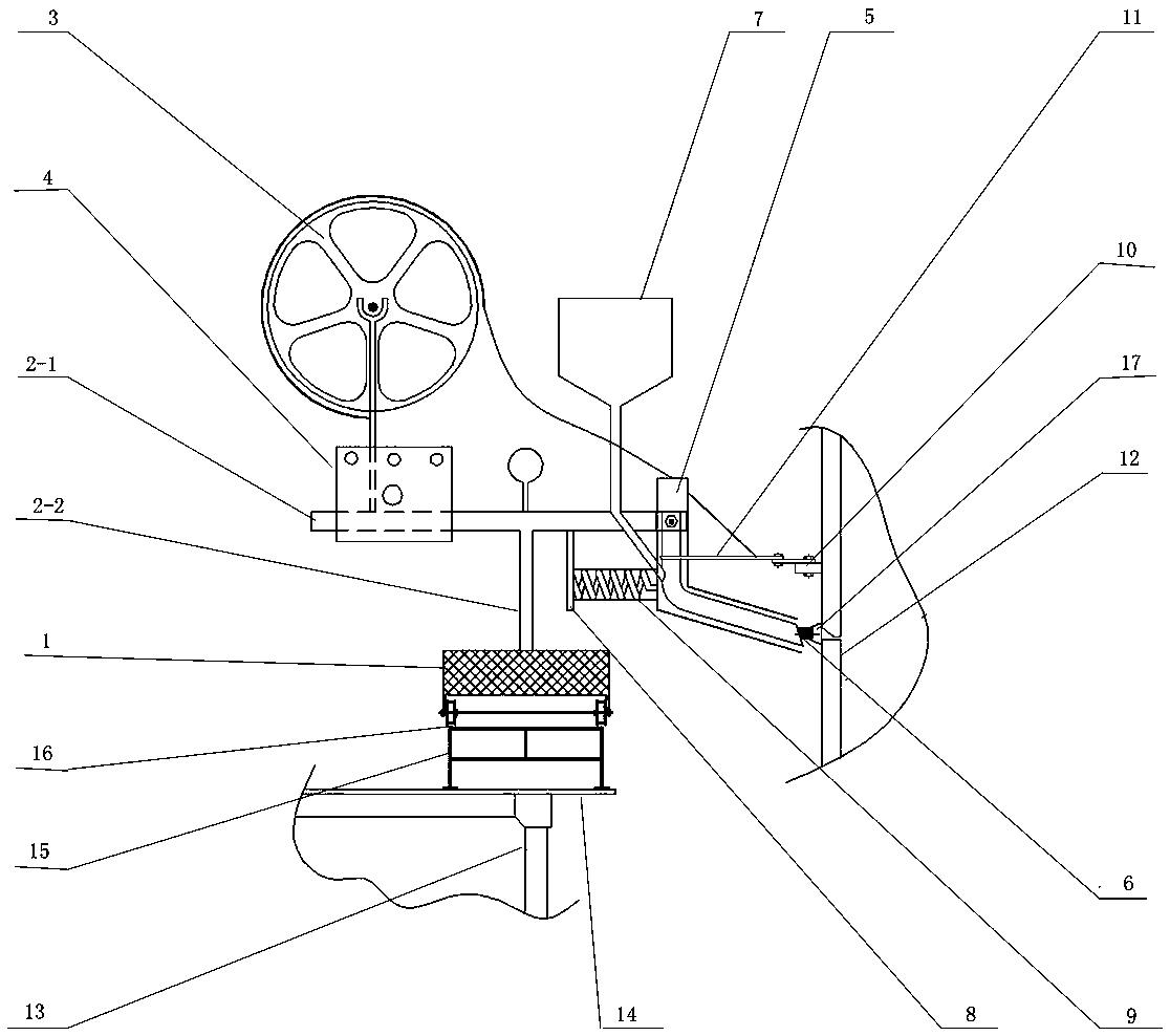
[0025] Such as figure 1 and figure 2 Shown, the welding method that the present invention is used for storage tank flip-chip method comprises the following steps:

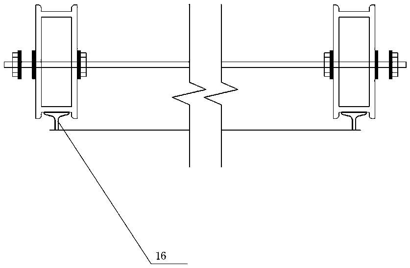
[0026] a. Prepare a submerged arc welding trolley 1: the submerged arc welding trolley 1 includes a body, two sets of wheels symmetrically arranged at the bottom of the body and a mounting bracket arranged on the top of the body. The mounting bracket includes a horizontal beam 2-1 and The column 2-2 arranged vertically, the beam 2-1 and the column 2-2 are vertically connected. Each axial end of each wheel of the submerged arc welding trolley is provided with a limiting ring whose outer diameter is larger than the outer diameter of the wheel, and the limiting ring is integrally formed with the corresponding end of the wheel.

[0027] b. A welding wire reel 3 and a control box 4 for controlling the welding operation are installed at one end of the beam 2-1, and a welding tip adjustment tube 5 is rotatably connecte...

Embodiment 2

[0033] Such as figure 1 and figure 2 As shown, the welding device used in the storage tank flip-chip method of the present invention includes a submerged arc welding trolley 1, a support frame 13 arranged in a circumferential direction on the outside of the storage tank 12, and a welding machine walking track 16 installed on the top of the support frame 13, The submerged arc welding trolley 1 includes a vehicle body, two sets of wheels symmetrically arranged at the bottom of the vehicle body and a mounting bracket arranged on the top of the vehicle body. The mounting bracket includes a horizontal beam 2-1 and a vertical column 2-2, and the beam 2- 1 is vertically connected with column 2-2. Each axial end of each wheel of the submerged arc welding trolley is provided with a limiting ring whose outer diameter is larger than the outer diameter of the wheel, and the limiting ring is integrally formed with the corresponding end of the wheel.

[0034] One end of the crossbeam 2-1...


PUM


Abstract

The invention provides a soldering method and soldering device for storage tank flip method, the soldering method comprises the steps of a, preparing a trolley for a bury arc soldering machine; b, rotationally connecting a soldering tip monitor pipe at the other end of the cross beam, mounting the soldering tip at the other end of the soldering tip monitor pipe; c, mounting a spring between a spring back plate and the soldering tip monitor pipe; d, fixedly mounting a soldering tip assist walk mechanism in the middle of the soldering tip monitor pipe; e, fixedly mounting a ring shape soldering machine walk rail set along the circumferential direction through a screw bolt at the top end of a rail installation support; f, placing the trolley of the bury arc soldering machine on the soldering machine walk rail, before the soldering, the operation staff turning around the soldering tip monitor pipe and keeping aligned an opening of the soldering tip and a soldering seam, adjusting the walk monitor wheel and keeping connected with a storage tank side wall steel, switching on a control box to start the soldering operation. The soldering method and the soldering device produces good effects in the method of automatic bury arc soldering and non bury arc automatic soldering in the flip large scale steel structure storage tank scheme.

Description

technical field [0001] The invention relates to a welding system used in the storage tank inversion method, in particular to a welding method and a welding device used in the storage tank inversion method. Background technique [0002] At present, the flip-chip method is a commonly used installation method for large and medium-sized storage tanks. The flip-chip method is to install the tank roof first, install the wall panels from the uppermost strip down, and finally weld them to the bottom plate. Among them, the flip-chip automatic welding, as a safe and efficient installation solution, has been widely used in the field of large steel structure storage tank installation. However, due to the limitation of its own characteristics, the welding equipment in this solution has a large equipment volume. , low welding efficiency and high construction costs. Contents of the invention [0003] One of the objects of the present invention is to provide a welding method for the stor...

Claims


Application Information

Patent Timeline
Patent Type & Authority Patents(China)
IPC IPC(8): B23K9/18B23K9/32
CPCB23K9/0026B23K9/18B23K9/32B23K2101/125
Inventor 石勇齐晓艳刘超
Owner CHINA MCC20 GRP CORP
Why Eureka
Try Eureka