Exhaust frame of density plate pre-pressing machine

A pre-press, MDF technology, applied in household components, flat products, household appliances, etc., can solve the problems of belt deviation, uncontrollable impact on the health of clean production personnel, and affecting the continuous operation of equipment.

Active Publication Date: 2017-02-22
SUZHOU SUFOMA MACHINERY
View PDF18 Cites 5 Cited by
  • Summary
  • Abstract
  • Description
  • Claims
  • Application Information

AI Technical Summary

Problems solved by technology

At the same time, during the continuous compression of the slab, both sides of the slab will spread outward, and wall panels with baffle blanks are installed on both sides of the introduction. When the slab is stretched and compressed to the wall panels on both sides, the slabs on both sides will The gas and fibers in the air will also fly out from the gap between the wallboard and the side of the introduction section. Therefore, during the production process, fibers are easy to accumulate above the introduction section. If the accumulated fibers are not cleaned regularly, they will be caught in the mesh belt. Between the belt and the transmission roller, it will cause the belt to deviate, which will seriously cause the belt to tear and affect the continuous operation of the equipment; at the same time, due to the overflow of gas and fibers from the introduction section, it will seriously pollute the working environment and sanitation of the site, which will affect the clean production and operation of the site. Uncontrollable impact on personnel health

Method used


Image

  • Exhaust frame of density plate pre-pressing machine
  • Exhaust frame of density plate pre-pressing machine
  • Exhaust frame of density plate pre-pressing machine

Examples


Embodiment Construction

[0014] The exhaust rack of the density plate pre-pressing machine of the present invention will be further described in detail below in conjunction with the accompanying drawings and specific embodiments.

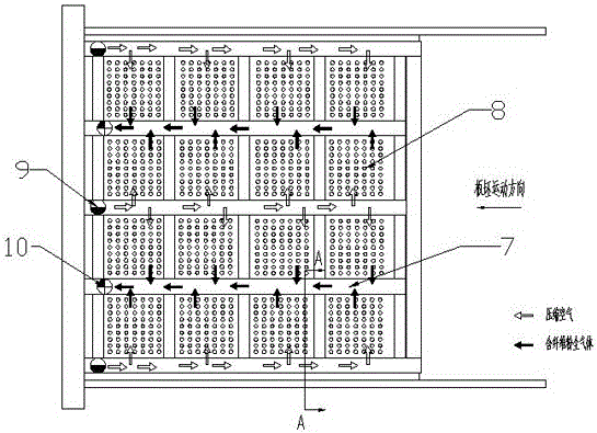
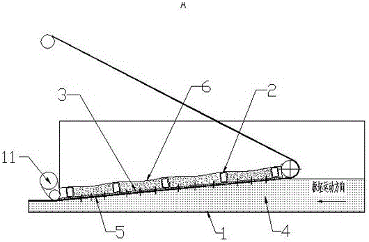
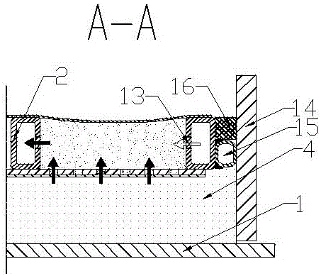
[0015] As shown in the figure, the density board pre-pressing machine exhaust rack of the present invention includes a horizontally arranged conveyor belt 1 and an introduction frame 2 with an inclined angle between the conveyor belt and the conveyor belt. The introduction frame is a frame structure, and the introduction The bottom end of the frame 2 is provided with a rotating shaft 11, and the introducing frame 2 can be flipped around the rotating shaft to adjust the angle. There is a breathable mesh belt 5 that can run synchronously with the conveyor belt under the blank 4 and the mesh plate 3. When in use, the blank 4 moves forward under the drive of the conveyor belt 1, and the guide frame 2 can turn up and down around the rotating shaft 10 , adjust the inclination ang...


PUM


Abstract

The invention discloses an exhaust frame of a density plate pre-pressing machine. The exhaust frame comprises a horizontally-arranged conveying belt and a guiding-in frame, wherein the guiding-in frame is arranged above the conveying belt, the inclination angle is formed between the guiding-in frame and the conveying belt, a layer of mesh plate is arranged at the lower portion of the guiding-in frame, a slab is placed above the conveying belt, a ventilation net belt capable of running synchronously with the conveying belt is arranged below the mesh plate, and a sealing cover is arranged at the upper portion of the guiding-in frame. The guiding-in frame is provided with frame grids longitudinally and transversely arranged. A negative pressure cavity is formed between each frame grid and the sealing cover at the upper portion of the guiding-in frame, a negative pressure cavity is formed between each frame grid and the mesh plate at the lower portion of the guiding-in frame, and each negative pressure cavity is provided with an air inlet and an air outlet. After the above structure is adopted, the problems about dust removing and sealing between the guiding-in frame and baffles on the two sides and the upper surface of the guiding-in frame are solved, and fiber is not prone to leaking from the two sides of a guiding-in section; meanwhile, gas exhausted from the mesh plate of the guiding-in frame and the fiber escaping from the mesh plate of the guiding-in frame are removed, the fiber is prevented from being accumulated above the guiding-in section, and the fiber is effectively removed.

Description

technical field [0001] The invention relates to an artificial board production equipment, in particular to a density board pre-pressing machine exhaust rack applied in a medium density board production line. Background technique [0002] In the production process of MDF, it is necessary to continuously pre-press the fluffy slab into a slab with a certain thickness and strength, and the pre-pressing of the slab is realized by a continuous pre-pressing machine. In the prior art, the introduction section of the continuous pre-pressing machine forms a certain inclination angle with the traveling direction of the slab when working, so as to gradually compress the fluffy slab and discharge the gas in the fluffy slab. A mesh plate is installed on the contact surface between the introduction section and the slab, and the gas generated during the process of compressing the slab is discharged through the mesh of the mesh plate, and some fine fibers run out with the airflow and accumul...

Claims


Application Information

Patent Timeline
Patent Type & Authority Applications(China)
IPC IPC(8): B27N3/08
CPCB27N3/086
Inventor 沈锦桃邹华东岳群飞沈毅林启平
Owner SUZHOU SUFOMA MACHINERY
Why Eureka
Try Eureka