Silicon wafer line cutter winding displacement mechanism

A cutting machine and silicon wafer technology, applied in grinding machines, fine working devices, working accessories, etc., can solve the problems of unreasonable air seal design, high maintenance frequency, easy damage of bearings, etc., to reduce maintenance costs and disconnection rate , Improve the running stability, improve the effect of fastening rigidity

Active Publication Date: 2017-02-22
江苏美科太阳能科技股份有限公司
View PDF9 Cites 0 Cited by
  • Summary
  • Abstract
  • Description
  • Claims
  • Application Information

AI Technical Summary

Problems solved by technology

[0004] At present, the end face of the bearing box of the wire arrangement mechanism of the silicon wafer line cutting machine is not sealed, the air seal design is unreasonable, and the cutting fluid is easy to enter the bearing box, causing the bearing to be easily damaged, the maintenance frequency is high, and the wire is broken

Method used


Image

  • Silicon wafer line cutter winding displacement mechanism
  • Silicon wafer line cutter winding displacement mechanism
  • Silicon wafer line cutter winding displacement mechanism

Examples


Embodiment Construction

[0027] The specific embodiments of the present invention will be further described below in conjunction with the accompanying drawings.

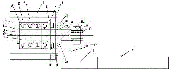
[0028] A wire arranging mechanism for a silicon wafer wire cutting machine, including a wire arranging roller, a roller shaft and a roller bracket, wherein the wire arranging roller is located on one side of the roller bracket, and a gasket is arranged between the roller bracket and the roller bracket. The gasket is arranged on the outside of the wire arranging drum, and the outside of the wire arranging roller is provided with a polyurethane bushing, and one side of the polyurethane bush is arranged adjacent to the gasket;

[0029] A cavity is provided in the cable arrangement drum, a mounting groove is provided on one side of the cavity, and a circlip groove is provided on the other side, and a circlip is provided in the circlip groove, and the width of the circlip groove is d1 , the distance from the circlip groove to one side of the cabl...


PUM


Abstract

The invention relates to a silicon wafer line cutter winding displacement mechanism which comprises a winding displacement roller, a rolling shaft and a roller bracket; the winding displacement roller is internally provided with a cavity; a mounting groove is formed in one side of the cavity; a clamping spring groove is formed in the other side of the cavity; the roller bracket comprises a vertical rack and a horizontal rack; a mounting hole, a first notch and a second notch are formed in the vertical rack; first external threads, second external threads and a convex plate are arranged on the roller; the roller is externally provided with a mounting nut, a bushing and a shaft cap, and is internally provided with a through hole; an air pipe connector is arranged on one side of the through hole; the other side of the through hole communicates with the mounting groove; and a plurality of bearings are arranged between the roller and the cavity of the winding displacement roller, and are internally provided with air guide holes. The silicon wafer line cutter winding displacement mechanism is reasonable in structure and convenient to mount, and the increasing of an equipment utilization rate and the reduction of the maintenance cost and a line broken rate are facilitated.

Description

technical field [0001] The invention relates to a wire arrangement mechanism of a silicon wafer wire cutting machine, which belongs to the technical field of silicon wafer processing in the photovoltaic industry. Background technique [0002] Multi-wire cutting technology is a relatively advanced silicon wafer processing technology in the world at present. Its principle is to use a high-speed moving steel wire to drive the cutting blade attached to the steel wire to rub against hard and brittle materials such as semiconductors to achieve cutting. Purpose. Compared with the traditional knife saw blade, grinding wheel and internal circle cutting, the wire cutting technology has the advantages of high efficiency, high production capacity and high precision. [0003] During the cutting process, the steel wire is guided by more than a dozen wire pulleys to form a wire net on the main wire roller, and the workpiece to be processed is fed through the rise and fall of the worktable...

Claims


Application Information

Patent Timeline
Patent Type & Authority Applications(China)
IPC IPC(8): B28D5/04B28D7/00B24B27/06
CPCB24B27/0633B28D5/045B28D7/00
Inventor 黄琳王海庆
Owner 江苏美科太阳能科技股份有限公司
Why Eureka
Try Eureka