Valve stem laser marking apparatus

A laser marking and valve technology, which is used in typewriters, printing and other directions, can solve the problems of easy falling off and wear of markings, inability to mark the date of mixing, and achieve the effects of marking not easy to fall off, automatic continuous marking and high processing efficiency.

Inactive Publication Date: 2017-02-22
BAOLONG ANHUI AUTO PARTS
View PDF9 Cites 4 Cited by
  • Summary
  • Abstract
  • Description
  • Claims
  • Application Information

AI Technical Summary

Problems solved by technology

[0004] At present, for the valve, the production company, valve model, mold number and die hole number are engraved on the vulcanization mold. After the valve is vulcanized, the embossed characters printed by the mold can be left on the head, but Due to the relative fixedness of the mold, it is impossible to mark the information such as the rubber mixing date, vulcanization date and expiration date that change dynamically with the product batch in this way. The disadvantage of using pigment printing or spray printing to make marks is that the marks are not easy to use during installation and use. Easy to shed and wear

Method used


Image

  • Valve stem laser marking apparatus
  • Valve stem laser marking apparatus
  • Valve stem laser marking apparatus

Examples


Embodiment Construction

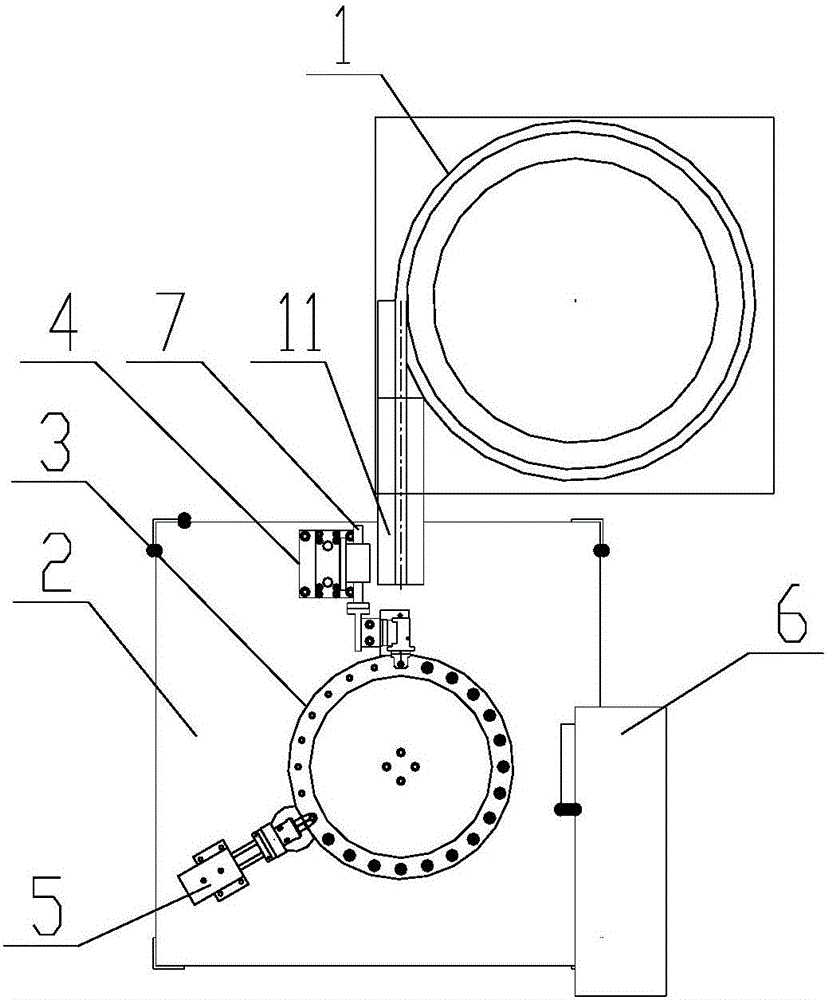
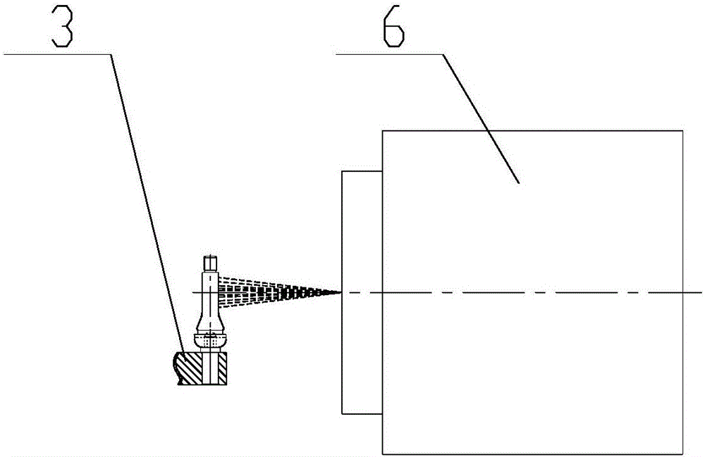
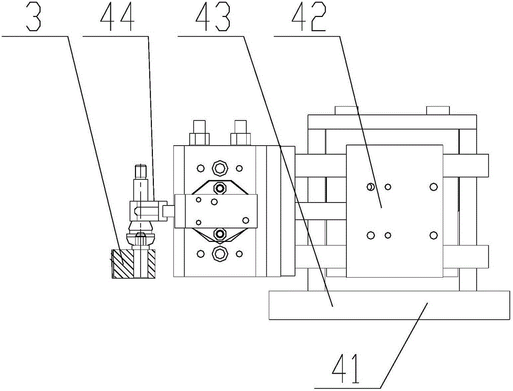
[0022] Such as Figures 1 to 3 as shown, figure 1 It is a structural schematic diagram of a valve laser marking device proposed by the present invention, figure 2 It is a structural schematic diagram of a laser marking mechanism of a valve laser marking device proposed by the present invention, image 3 It is a structural schematic diagram of a feeding manipulator of a valve laser marking device proposed by the present invention.

[0023] refer to figure 1 with 2 , a valve laser marking device proposed by the present invention, comprising: a vibrating feeding mechanism 1, a workbench 2, a loading tray 3, a feeding manipulator 4, a feeding manipulator 5, a laser marking mechanism 6, and a driving mechanism;

[0024] The workbench 2 is provided with a vertically arranged first rotating shaft, and the loading tray 3 is rotatably mounted on the workbench 2 through the first rotating shaft. The driving mechanism is connected with the loading tray 3 to drive the loading tray 3 ...


PUM


Abstract

The invention discloses a valve stem laser marking apparatus. A material carrying disk is provided with a feeding station, a blanking station and a marking station in the periphery thereof. A vibration feeding mechanism is disposed on one side of the feeding station of a work bench. A feeding manipulator is arranged at the feeding station for feeding a valve stem of a blanking channel for blanking to a valve stem receiving position of the material carrying disk at the feeding station. A laser marking mechanism is disposed at the marking station for marking the valve stem which is arranged at the marking station. A blanking manipulator is disposed at the blanking station for blanking the valve stem which is at the blanking station and is marked. The valve stem laser marking apparatus has reasonable structure and design and realizes the switching of stations during feeding, marking and blanking through the rotation of the material carrying disk, such that the valve stem can conduct automatic and continuous marking, has high processing efficiency, and performs firm marking that is not easy to fall.

Description

technical field [0001] The invention relates to the technical field of valve processing, in particular to a valve laser marking device. Background technique [0002] Compared with metal valves, valves occupy a large proportion in the automotive field because of their convenient installation and low price. After installing the tire pressure monitoring system on the valve, there are new requirements for its reliability. In order to ensure safe use, the valve must have a strict information identification system, which not only needs to identify the production date and expiration date of the valve, but also trace all the background information of the valve based on this information. [0003] After the valve is made, no matter it is used or stored, the rubber body on it will gradually age and become invalid with the passage of time. Therefore, for the user to use the valve safely, it is very important to know the rubber mixing date, vulcanization date and validity period of the...

Claims


Application Information

Patent Timeline
Patent Type & Authority Applications(China)
IPC IPC(8): B41J2/435B41J3/407
CPCB41J2/435B41J3/407
Inventor 王贤勇肖付瑞胡小聪薄立满贾立甫李鹏
Owner BAOLONG ANHUI AUTO PARTS
Why Eureka
Try Eureka