Drilling type continuous sand blasting device

A technology of sand flushing and sand flushing fluid, which is applied to drill bits, drill pipes, drill pipes, etc., can solve the problems that the sand cleaning effect of the hard sand column is not obvious, the circulation cannot be established, and the sand fishing operation is not easy to succeed. energy, improve sand washing efficiency, and reduce the effect of bottom hole pressure difference

Inactive Publication Date: 2017-02-22
SOUTHWEST PETROLEUM UNIV
View PDF8 Cites 12 Cited by
  • Summary
  • Abstract
  • Description
  • Claims
  • Application Information

AI Technical Summary

Problems solved by technology

The key to hydraulic sand washing operation is to establish circulation in the wellbore, so that the formation sand can be carried out of the well by the sand washing fluid. Leak directly into the formation; although low-density sand washing liquid or jet negative pressure sand washing can be used for normal circulation, the sand cleaning effect for severely consolidated hard sand columns is not obvious
The mechanical sand dredging technology does not require external working fluid circulation, will not pollute the oil layer, and is easy to operate, but when the bottom of the well is settled and consolidated to form a sand column, the sand dredging operation is often difficult to succeed
[0004] As can be seen from the above, there is currently no effective method to solve the problem of hard sand columns produced in the production of low-pressure oil and gas wells

Method used


Image

  • Drilling type continuous sand blasting device
  • Drilling type continuous sand blasting device
  • Drilling type continuous sand blasting device

Examples


Embodiment Construction

[0028] In order to make the purpose, technical solutions and advantages of the present invention clearer, the following technical solutions in the present invention are clearly and completely described. Obviously, the described embodiments are some embodiments of the present invention, rather than all embodiments. Based on the embodiments of the present invention, all other embodiments obtained by persons of ordinary skill in the art without creative efforts fall within the protection scope of the present invention.

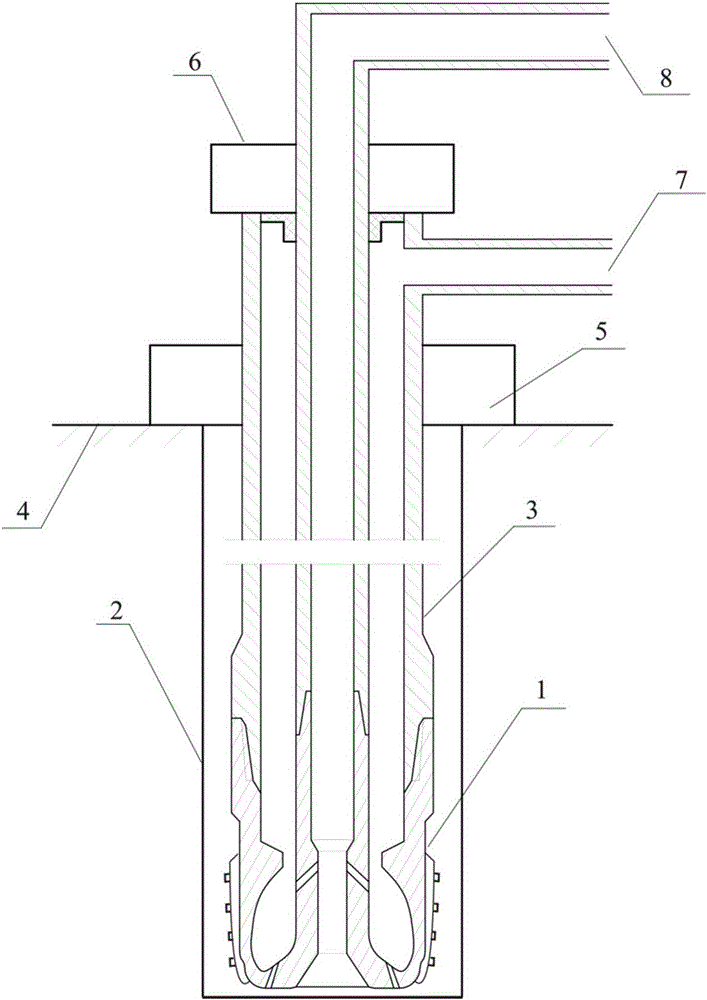
[0029] Such as Figure 1-Figure 4 As shown, the drillable continuous sand washing device of the present invention includes a sand washing drill bit 1, a double-walled drill string 3, a rotary sealing wellhead 5, a rotary driving device 6, a sand washing fluid manifold 7, and a sand carrying fluid manifold 8.

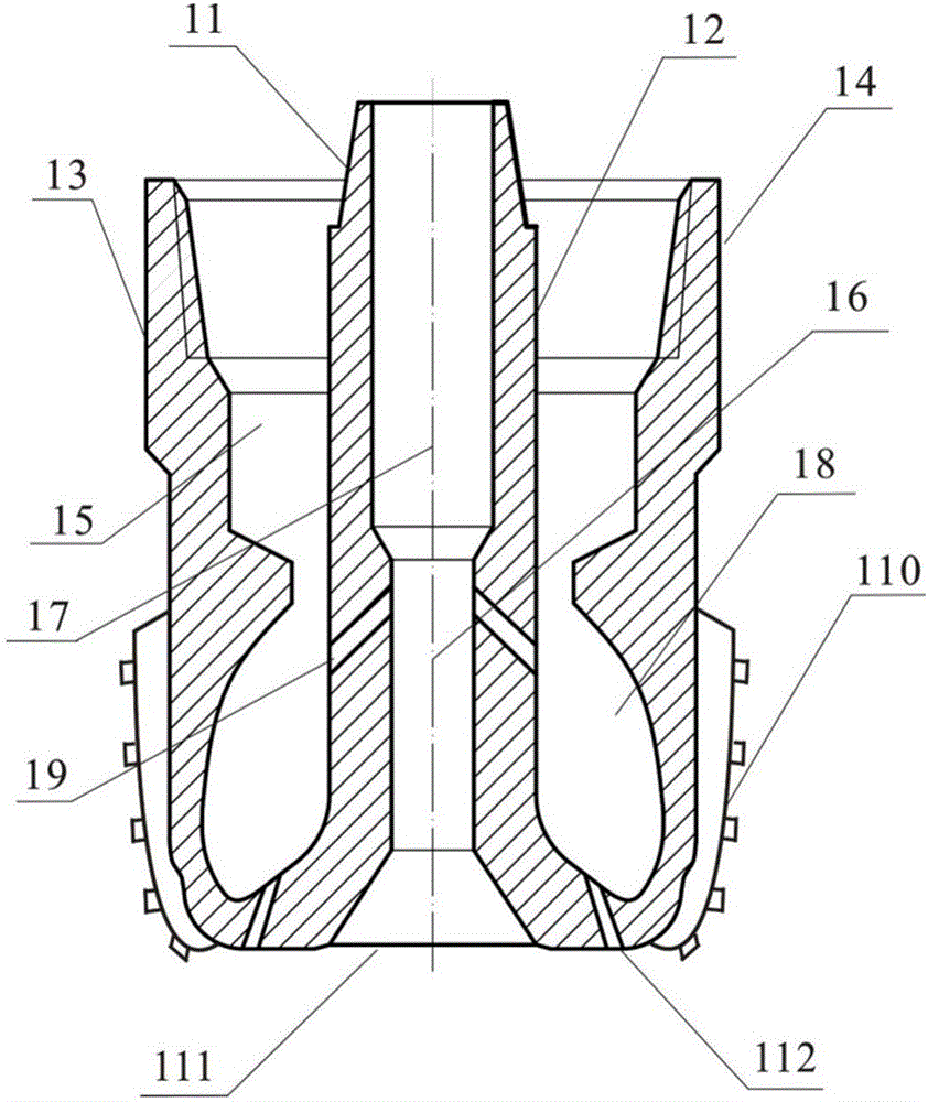
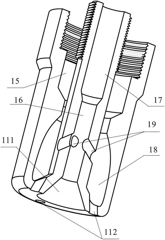
[0030] The sand washing drill bit 1 includes a drill bit body 13, a drill bit body joint 14, a drill bit inner body 12, a drill bit inner joint 11, a cutti...


PUM


Abstract

The invention provides a drilling type continuous sand blasting device, comprising a sand blasting drill bit, a dual-wall drilling pillar, a rotational sealing well head, a rotational driving device, a sand blasting fluid manifold, and a sand carrying fluid manifold; the sand blasting drill bit includes a drill bit body and an inner drill bit body; the rotational driving device drives the dual-wall drilling pillar to rotate so as to drive the sand blasting drill bit to rotate and cut the hardware sand pillar at the bottom; a high-pressure shocking cavity with a multi-curve cavity is formed between the inner wall of the lower end of the drill bit body and the outer wall of the internal drill bit; a part of sand flushing fluid in the high pressure shocking cavity can provide suction negative pressure through a high pressure jet flow generated from a backward jet flow nozzle; thus on the one hand, normal circulation sand carrying of a low pressure well can be guaranteed; on the other hand, the settled sand at the bottom is isolated from the well bottom, so as to benefit sand carrying; the other part of sand blasting fluid is sprayed from the drill bit nozzle, asymmetry jet flow is formed, thus it is good for making the strewing sand at the well bottom enter the sand carrying suction cavity and improving the sand carrying efficiency. The device can guarantee the safety of oil gas well while effectively complete the cleaning work of the hard sand pillar of the low-pressure oil well.

Description

technical field [0001] The invention relates to the technical field of machinery, in particular to a drilling type continuous sand washing device. Background technique [0002] Formation sand production is one of the unavoidable and important problems in the development and production of oil and gas fields. Due to factors such as long production time, high recovery degree and severe reduction of reservoir pressure coefficient in oil fields in the central and eastern my country, formation sand production is particularly serious. According to statistics, the sand production wells in Jianghan Oilfield account for about 50% of the total production wells, and the number of workover operations caused by formation sand production in the oilfield accounts for 45%-50% of the total workover times, which greatly increases the production cost of the oilfield. Formation sand deposits in the wellbore to form a sand column, flooding the production layer, resulting in a decrease in producti...

Claims


Application Information

Patent Timeline
Patent Type & Authority Applications(China)
IPC IPC(8): E21B21/00E21B10/60E21B10/61E21B10/43E21B17/18
CPCE21B21/00E21B10/43E21B10/602E21B10/61E21B17/18
Inventor 邓丽王国华秦大伟谭军董学成黄燊熊继有
Owner SOUTHWEST PETROLEUM UNIV
Why Eureka
Try Eureka