Eddy current heating oil shale underground in-situ mining method
A technology of eddy current heating and in-situ mining, which is applied in the fields of mining fluid, induction heating, earthwork drilling, etc., can solve the problems of polluting groundwater in the environment, high construction intensity, complex process, etc., achieve high energy utilization rate, accelerate the heating process, The effect of reducing heating costs
- Summary
- Abstract
- Description
- Claims
- Application Information
AI Technical Summary
Problems solved by technology
Method used
Image
Examples
Embodiment 1
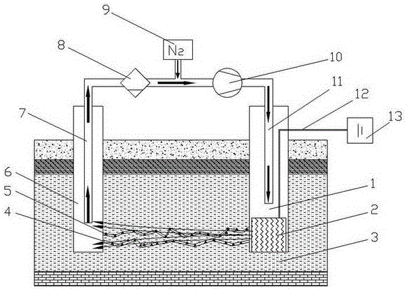
[0036] a. If figure 1 As shown, in the Nong'an area of Jilin Province, a target oil shale formation has a burial depth of 60m-70m at three positions, and a gas injection well with a diameter of 500mm is drilled from the surface for 1 to 70m;
[0037] b. Then perform hydraulic fracturing in the 60m-70m section to produce hydraulic fracturing cracks 4, the fracturing radius is not less than 10m, and iron particles 5 with a diameter of 0.8-1mm are used as proppants during fracturing;
[0038] c. Then drill a production well 6 with a diameter of 500mm and a depth of 70m at a position 5m away from the gas injection well on the surface;
[0039] d. Place the eddy current effect strong magnetic field generator 2 connected to the ground power supply 13 through the high temperature cable 12 at the bottom of the gas injection well. The effective length of the eddy current effect strong magnetic field generator 2 in the gas injection well is 10m, and the direction of action is towards ...
Embodiment 2
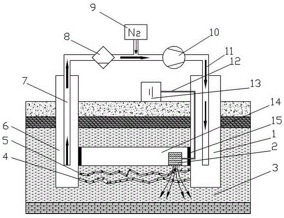
[0047] a. If figure 2 As shown, in the Huadian area of Jilin Province, a target oil shale formation has a burial depth of 80m-85m at three positions, and a gas injection well with a diameter of 500mm is drilled from the surface for 1 to 85m;
[0048] b. Then perform hydraulic fracturing in the 80m-85m section to produce hydraulic fracturing cracks 4, the fracturing radius is not less than 20m, and iron particles 5 with a diameter of 0.8-1mm are used as proppants during fracturing;
[0049] c. Then drill a production well 6 with a diameter of 500mm and a depth of 85m at a position 12m away from the gas injection well on the surface;
[0050] d. Drill a through horizontal well 14 from the gas injection well 1 to the production well at a depth of 80 meters;
[0051] e. place the eddy current effect strong magnetic field generator 2 connected to the ground power supply 13 through the high temperature cable 12 in the horizontal well 14, the eddy current effect strong magnetic f...
Embodiment 3
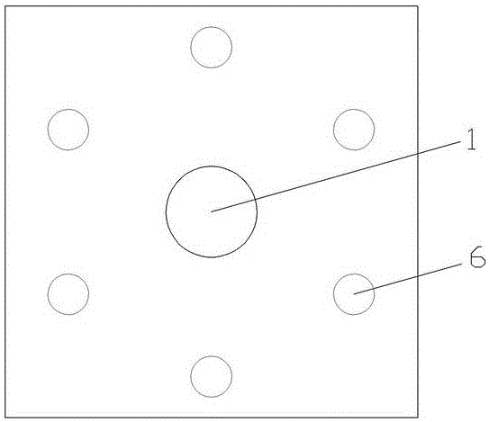
[0060] Such as image 3 As shown, the main technical solutions of this embodiment are the same as those of Embodiment 1, and the features not explained in this embodiment are explained in Embodiment 1, and will not be repeated here. The difference between this embodiment and Embodiment 1 is that multiple production wells 6 are used, arranged in a circular array around the gas injection well 1, and the eddy current effect strong magnetic field generator 2 is placed at the bottom of the gas injection well 1, and can be sent to each production well 6 Directional heating; this way of well layout can reduce equipment and engineering investment, thereby reducing costs.
PUM
| Property | Measurement | Unit |
|---|---|---|
| Particle size | aaaaa | aaaaa |
Abstract
Description
Claims
Application Information
 - R&D
- Intellectual Property
- Life Sciences
- Materials
- Tech Scout
- Unparalleled Data Quality
- Higher Quality Content
- 60% Fewer Hallucinations
Browse by: Latest US Patents, China's latest patents, Technical Efficacy Thesaurus, Application Domain, Technology Topic, Popular Technical Reports.
© 2025 PatSnap. All rights reserved.Legal|Privacy policy|Modern Slavery Act Transparency Statement|Sitemap|About US| Contact US: help@patsnap.com


