
Combined pressure-reducing well pipe used in shield tunneling interval and its installation method

An installation method and technology for decompression wells, which are applied in earthwork drilling, mining equipment, tunnels, etc., can solve problems such as inability to arrange decompression well pipes, and achieve the effects of low shear strength, convenient construction, and cost reduction

Active Publication Date: 2018-08-21
NO 2 CONSTR GRP CO LTD OF SHANGHAI CONSTR GRP
View PDF5 Cites 0 Cited by
  • Summary
  • Abstract
  • Description
  • Claims
  • Application Information

AI Technical Summary

Problems solved by technology

[0003] The purpose of the present invention is to provide a combined pressure-relief well pipe and its installation method for the shield tunneling section, which can solve the problem that the pressure-relief well pipe cannot be arranged in the orbital shield tunneling section

Method used


Image

  • Combined pressure-reducing well pipe used in shield tunneling interval and its installation method
  • Combined pressure-reducing well pipe used in shield tunneling interval and its installation method

Examples


Embodiment Construction

[0031] In order to make the above objects, features and advantages of the present invention more comprehensible, the present invention will be further described in detail below in conjunction with the accompanying drawings and specific embodiments.

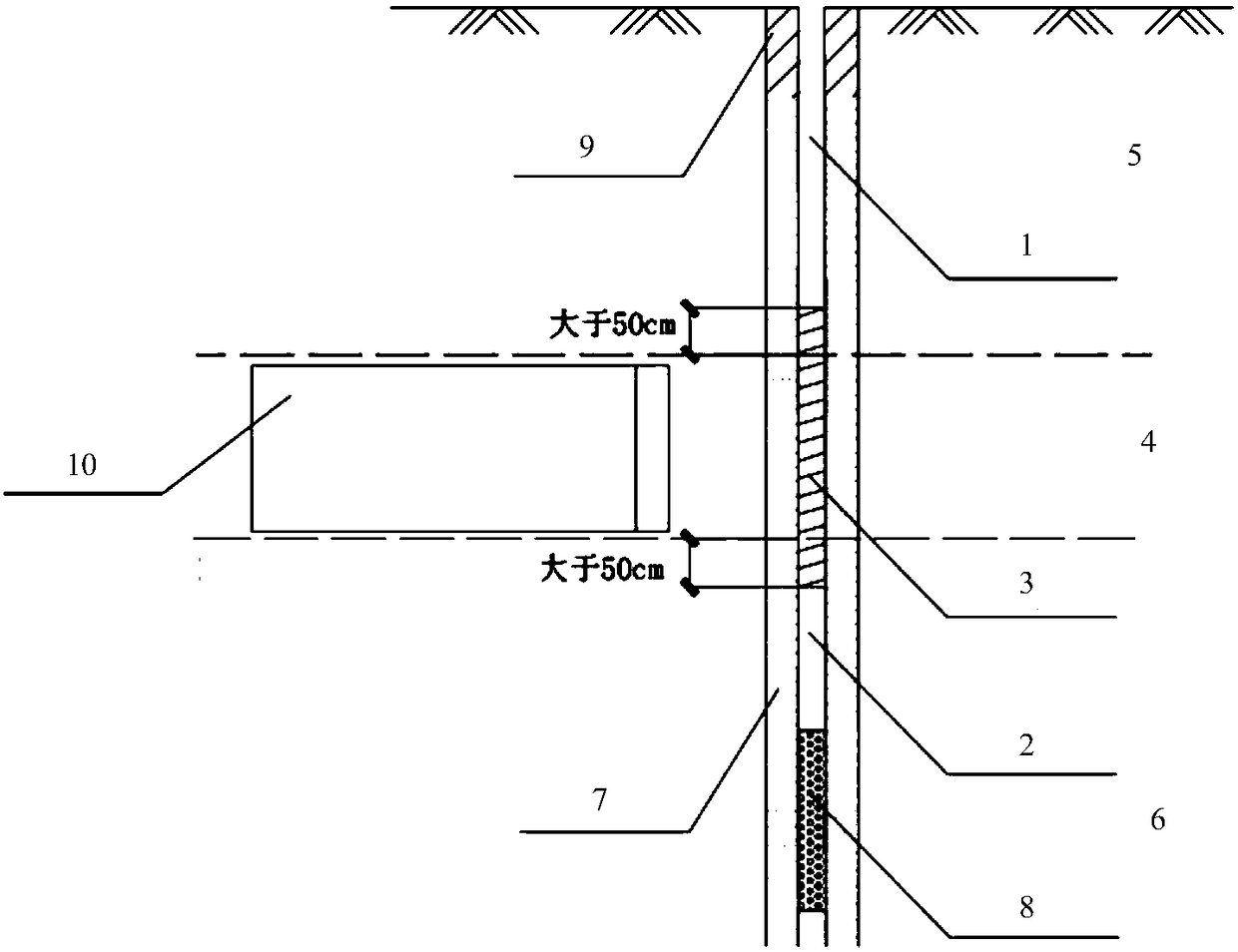
[0032] Such as figure 1 As shown, the present invention provides a combined pressure-relief well pipe used in the shield tunneling section, including:

[0033] The pressure-relief well pipes in the depth areas 5 and 6 of the non-shield machine 10 are made of steel pipe, and the pressure-relief well pipes in the depth area of ​​the non-shield machine construction include the first steel pipe pressure-relief well pipe 1 and the second steel pipe decompression well pipe 2;

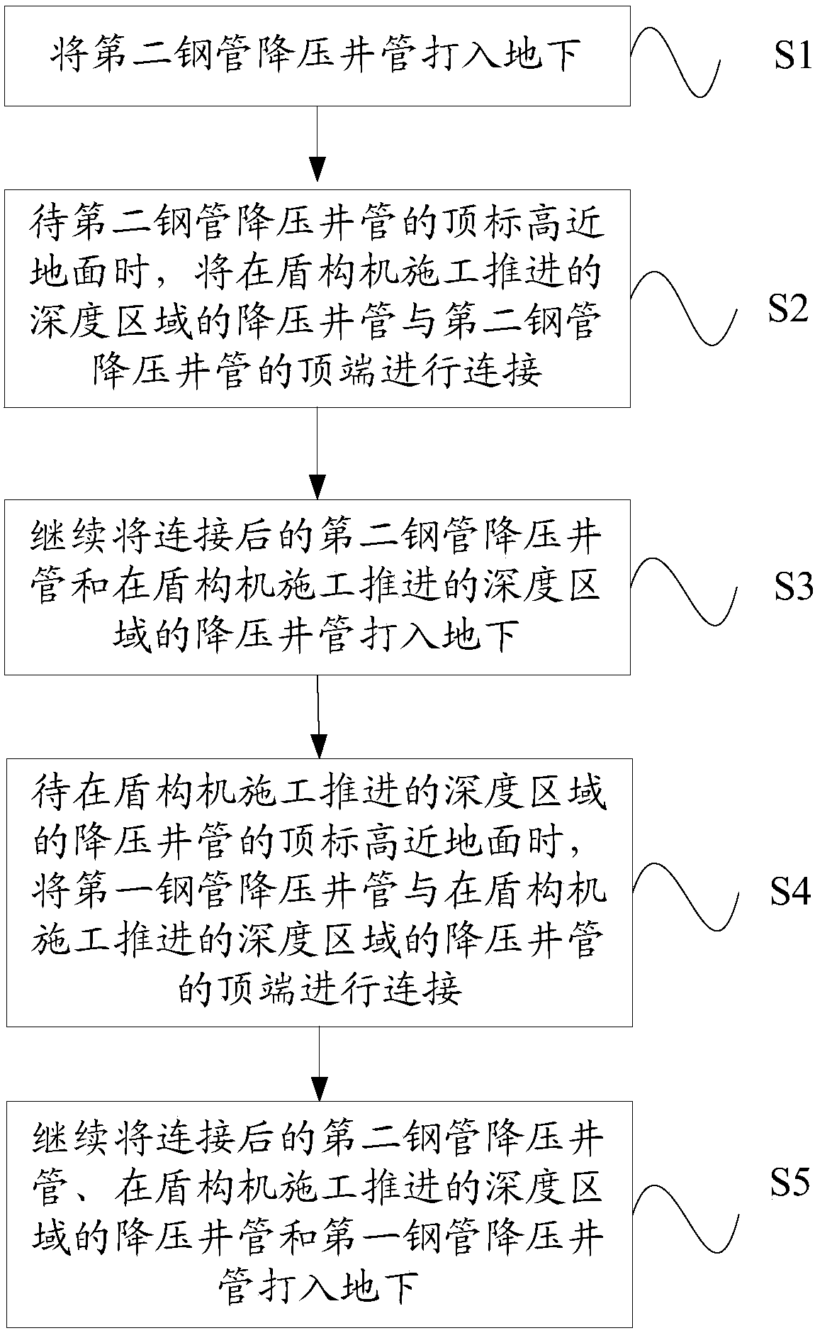
[0034] The pressure-relief well pipe 3 in the depth area 4 of the shield machine 10 construction advances is made of glass fiber reinforced plastic (FRP). The depressurization well pipe 1 is connected with the second steel pipe depressurization well pipe 2 . S...


PUM


Abstract

The invention provides a combined type pressure reduction well casing used for a shield excavation interval and a mounting method of the combined type pressure reduction well casing. A pressure reduction well casing body in a depth zone where a non-shield machine is used for construction and tunneling is made from a steel tube material and comprises a first steel tube pressure reduction well casing body and a second pressure reduction well casing body. A pressure reduction well casing body in a depth zone where a shield machine is used for construction and tunneling is made from a glass reinforced plastic material, the upper end and the lower end of the pressure reduction well casing body in the depth zone where the shield machine is used for construction and tunneling are connected with the first steel tube pressure reduction well casing body and the second pressure reduction well casing body correspondingly. The pressure reduction well casing body in the depth zone where the shield machine is used for construction and tunneling is made from the glass reinforced plastic material and can be cut off and crushed during shield tunneling, shield mechanical failures cannot be caused, smooth conduction of shield excavation construction is ensured, the limitation that the casing cannot be arranged in the shield excavation interval can be broken, the novel water pressure reduction well casing does not influence the shield machine, arrangement of downcast pipes during project construction is facilitated, and the construction efficiency is improved.

Description

technical field [0001] The invention relates to a combined pressure-reducing well pipe used in a shield tunneling section and an installation method thereof. Background technique [0002] The traditional pressure-relief well pipe is made of steel. For example, if the traditional pressure-relief well pipe is arranged in a tunnel or subway area, when the shield machine advances to the position of the pressure-relief well pipe, it is difficult to crush the steel and easily cause mechanical failure. Therefore, it is usually forbidden to arrange dewatering well pipes (depressurization well pipes) in the excavation section of the existing orbital shield machine, so as not to affect the progress of the shield machine. Contents of the invention [0003] The purpose of the present invention is to provide a combined pressure-relief well pipe and its installation method for the shield tunneling section, which can solve the problem that the pressure-relief well pipe cannot be arranged...

Claims


Application Information

Patent Timeline
Patent Type & Authority Patents(China)
IPC IPC(8): E21D9/06
CPCE21D9/06
Inventor 龙莉波丁义平戚健文宋毅
Owner NO 2 CONSTR GRP CO LTD OF SHANGHAI CONSTR GRP
Learn More